4
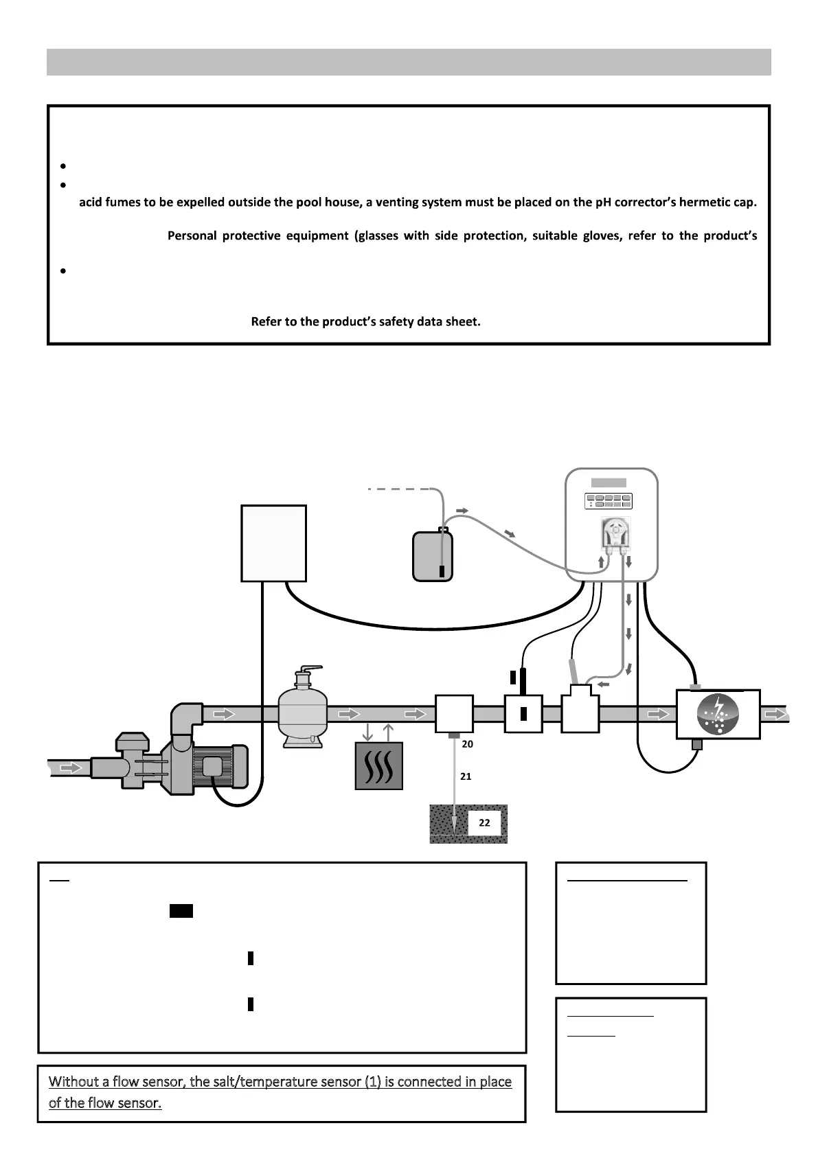
3. INSTALLATION DIAGRAM
I
The electrical connections at cell-level must not point upwards, to avoid any deposits of water or humidity on them.
The pH corrector container must be kept 2 metres away from any electrical device or any other chemicals. In order for
Failure to follow these instructions may lead to abnormal oxidation of metal parts, possibly resulting in complete
device failure.
safety data sheet) must be worn whenever handling the pH corrector or the injection circuit.
Never use hydrochloric acid, as this may lead to irreversible damage to the device and void the warranty. Only use a
sulphuric acid- or alkali-based pH corrector product recommended by your professional dealer. Please note that use of
a multi-acid pH corrector requires increased maintenance, and its use may also lead to premature wear of the pH
circuit and void the warranty.
4
6
KEY:
PROpilot SALT: white
With ORP option: white + black.
1: Flow sensor (optional)
2: Cell
3: Electronics unit
4: Ballast filter
5: Peristaltic pump
6: ORP probe (optional)
7: pH probe
8: Avady probe holder
9: Saddle clamp
10, 11: Semi-rigid tubing
12: Salt/temperature/low water sensor (optional)
1
7
15
H
2
9
17
8
11
ELEMENTS NOT SUPPLIED:
13: Electricity supply
14: pH corrector container
15: Filter
16: Heat pump
17: Filtration pump
16
12
POOL GROUND KIT
(optional):
19: Support
20: Electrode
21: Copper cable
22: Ground rod
4
22
21
20
19
Without a flow sensor, the salt/temperature sensor (1) is connected in place
of the flow sensor.
 Loading...