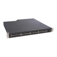
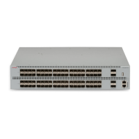
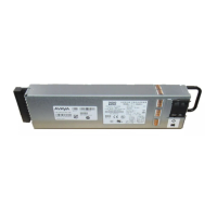
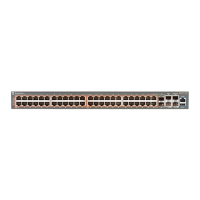
Figure 9: Attaching rubber footpads to a 5500 Series switch
2. Set the switch on a table or shelf as shown in
Figure 10: Ethernet Routing Switch
5000 Series on a table or shelf on page 64. Allow at least 2 inches (5.1
centimeters) on each side for proper ventilation and at least 5 inches (12.7
centimeters) at the back for power cord clearance.
Switch placement
Avaya Ethernet Routing Switch 5000 Series Installation December 2010 63

 Loading...


