Pro Tools | MTRX Studio Installation Guide24
5 Indicators (from top to bottom) — Displays the Mic/Inst input settings per channel when PRE (4) is ac-
tivated.
• EXT — Lights green to indicate sync lock to an external clock source, or flashes red to indicate that
sync is not locked.
• MIC — Indicates Mic input for the selected channel.
• INST — Indicates Instrument input for the selected channel.
• Link — Indicates that channels 1 and 2 are linked.
• Ø — Indicates phase invert for the selected channel.
• 48V — Indicates phantom power is enabled for the selected channel.
6 16 segmented LED meters indicating signal level of the selected source (analog, ADAT, or Dante) input
or output.
7 OUT button — Press to set the 16 segmented LED meters to display output levels for the selected source.
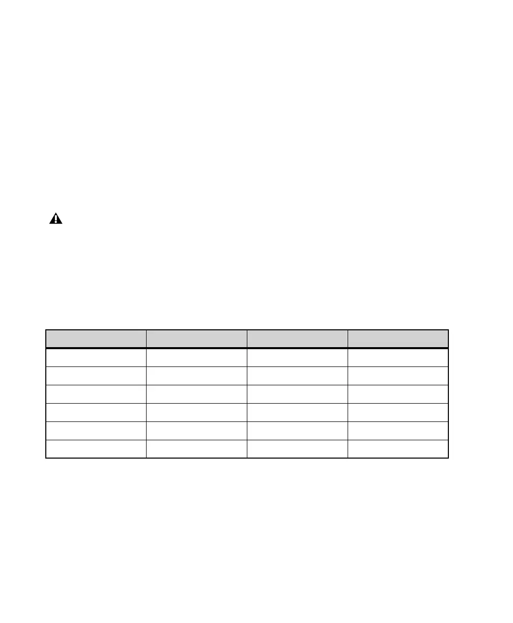
8 Meter button — Press to cycle between sources for the 16 segmented LED meters: analog, ADAT, and
Dante (1–4). The individual sources for metering are indicated by different colors in the meters and
channels numbers. The mapping is shown in table 1 below.
9 IN button — Press to set the 16 segmented LED meters to display input levels for the selected source.
10 CR, Monitor/Cue Level meter — Shows the level of the left and right signal of the control room output
or the monitor/cue output. The readout follows the selection made using the
Speaker (15), Headphone
(16), and
Select (14) buttons.
Note that levels for the Mic/Inst input channels (1/4-inch inputs on the front panel and XLR inputs on the
back panel) are not shown in the 16 segmented LED meters. Likewise, these meters do not show the levels
for the monitor outputs (1/4-inch jacks on the back panel).
Meter sources
Meter button push Color Viewed Channels Meter Number highlight
Mode 1 Light Blue Analog channels Light Blue
Mode 2 Dark Blue ADAT channels Dark Blue
Mode 3 Orange Dante channels 1–16 Orange, 1 White
Mode 4 Orange Dante channels 17–32 Orange, 2 White
Mode 5 Orange Dante channels 33–48 Orange, 3 White
Mode 6 Orange Dante channels 49–64 Orange, 4 White