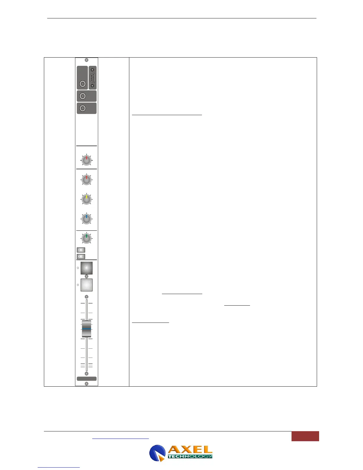
The telco module interfaces an external telephone hybrid with the console. A
separate hybrid for each Telco module will be required.
It has only one mono input (Receive), the other Jack connector being used for
the mix minus output (Send) to the telephone hybrid. The mix minus signal is the
programme output signal with the phone signal (caller’s voice) removed. The
SEND gain control adjusts in the +/- 15 dB range the level of mix-minus signal
which is sent to the telephone caller via the external telephone hybrid, while the
RECEIVE gain control adjusts in the +/- 15 dB range the level of the signal
incoming from telephone caller via the external telephone hybrid.
The ‘Hook’ button becomes the Line Hook Remote Divert control for
suitable hybrids via the remote connector.
A ‘RING’ LED (next to the Hook button) is provided for signaling of
incoming calls.
It features two gain controls, PFL, Master and Sub output select, hybrid
remote controls.
The engineer (or the presenter) can talk off-air with a caller (whilst the Main
programme is being output) via its own microphone (connected to Mono module
and routed as TB to Studio) or the TB microphone built-in into the Monitor
module..
In addition, two relays in the PWS offer the option of driving external red
light ‘Call’ indicators in the Studio / Ctrl Room. Two jumpers on the module
board select which relay (Relay 1 or Relay 2) will be activated by incoming
call signal (ref to par. 12.2 for jumper settings).
The PAN control determines the position of the signal within the stereo mix
image. Rotation fully anticlockwise feeds the signal solely to the Left mix bus,
while rotation clockwise sweeps the image to the Right mix bus.
The centre applies 0 dB of gain to both L & R signals.
ALPS N-type 90° ultra smooth 100 mm sliders are provided on series.
The scale shows the attenuation. Normal operating position is at the top ‘0’ mark,
providing overall 0 dB of gain.
On request, to notify at order, ALPS K series and K/VCA series sliders can be
also fitted, the last ones controlling the internal high quality VCA circuity. There is
no audio going through the VCA faders. VCA faders do not therefore suffer from
such severe noise and signal loss problems that conventional faders may have
when wear and tear causes the resistive surface to deteriorate. The benefit is
longer fader life, as the crackles and dropouts typical of the traditional audio
faders are smoothed out.
 Loading...