Do you have a question about the Axel Oxygen 4 and is the answer not in the manual?
Lists console frame sizes, model numbers, and specifications.
Details available Oxygen 4 modules, their article numbers, and models.
Describes fader options and script tray modules, highlighting quality and features.
Lists optional modules and states the manual's coverage.
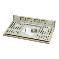
Provides visual representations of the Oxygen 4 console with 10 and 20 channel frames.
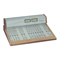
Shows pictures of Oxygen 4 consoles with VMH and 30 channel frames.
Introduces safety warnings and advises reading marked text to avoid warranty issues.
Details essential safety precautions for installation and operation, including electrical safety.
Provides instructions for inspecting equipment upon arrival and handling damage claims.
Lists basic tools required for installing the Oxygen 4 equipment.
Details power supply cable specs, wiring, and AC voltage setting procedure.
Guides users through safely replacing the power fuse in the unit.
Advises on lightning protection and the importance of ventilation for equipment operation.
Explains the crucial role of proper earthing for console safety and audio performance.
Provides guidance on selecting an optimal location for the console, considering convenience and interference.
Presents a block diagram illustrating the internal signal flow and connections within the Oxygen 4 console.
Describes factory presets for Mono, Telco, Stereo, and Monitor modules.
Provides step-by-step instructions for safely removing and installing modules.
Explains how to adjust input gain levels for optimal signal monitoring.
Introduces the Mono module, detailing its inputs, gain, EQ, routing, and PFL.
Explains jumper settings for Mono module functions like phantom power and TalkBack.
Details rear panel connections and the A/B switch for selecting inputs.
Explains the Gain, Parametric Equaliser, and Pan controls on the Mono module.
Describes Master-Sub routing, PFL button, and fader operation on the Mono module.
Introduces the Stereo module, covering dual inputs, EQ, routing, PFL, and Start/Stop interfaces.
Explains the 'START' optional interface for latched Start/Stop control, including its pin-out.
Details the 'SSIR' optional interface for momentary Start/Stop control, including its pin-out.
Describes Start/Stop relay configuration and interface operation for the SSIR option.
Details the SSIO interface pin-out for momentary Start/Stop control using opto-couplers.
Explains configuring Stereo module's Input B for Line or Phono sources using jumper settings.
Details rear panel inputs and the A/B switch for selecting between Input A and B.
Describes the Gain control on the Stereo module for adjusting input signal levels.
Explains the Equaliser, Balance, and Master-Sub routing controls on the Stereo module.
Details the PFL button and fader operation on the Stereo module.
Introduces the Telco module, its hybrid interface, gain controls, and remote functions.
Details the Telco module's remote interface connector, its connection, and pin-out.
Details rear panel connections and the Receive/Send level controls on the Telco module.
Describes the Hook switch, Ring LED, and Pan control functionality on the Telco module.
Explains Master-Sub routing switches and the PFL/Private button on the Telco module.
Describes the fader operation on the Telco module for channel attenuation.
Introduces the Telephone module, its built-in hybrid, gain controls, and line connections.
Details rear panel connections and provides guidelines for connecting telephone lines.
Shows the pin-out for the telephone line and tel set connectors on the module.
Describes the Receive, Send, Hook, Ring, and Pan controls on the Telephone module.
Explains Master-Sub routing switches and the PFL/Private button on the Telephone module.
Describes the fader operation on the Telephone module for channel attenuation.
Introduces the Master-Sub module, its main outputs, recording outputs, and routing capabilities.
Details rear panel connections and the Stereo/Mono mode switchers on the Master-Sub module.
Explains REC controls, Master routing switch, and PFL button on the Master-Sub module.
Describes the fader operation on the Master-Sub module for controlling the Sub channel level.
Introduces the Monitor module, covering its monitoring resources for various signals.
Explains jumper settings for configuring Studio outputs and enabling the built-in microphone.
Details rear panel connections and the Tuner level control on the Monitor module.
Describes Studio monitor section controls for selecting sources and adjusting output levels.
Details Control Room monitor section controls for selecting sources and adjusting output levels.
Explains the Talk Back button and built-in microphone for communication between control room and studio.
Details the headphone output jacks for the Studio and Control Room sections.
Shows power supply views and explains its components and functionality.
Details power supply relays and the mixer connection procedure.
Guides on AC voltage settings and provides troubleshooting steps for the power supply.
Explains meterbridge view, meter functions, and jumper settings for signal display.
Explains audio connection standards and provides XLR connection diagrams.
Shows diagrams for XLR-Jack and RCA unbalanced audio connections.
Details pin-outs for XLR microphone input and 1/4" jack connections for various modules.
Begins the step-by-step guide for changing or substituting modules in the Oxygen 4 console.
Continues the guide for safely removing modules from the Oxygen 4 console.
Continues the guide for disconnecting module connectors.
Concludes the guide on removing and mounting new modules in the Oxygen 4 console.
Provides the physical dimensions for different frame sizes of the Oxygen 4 console.
Lists detailed technical specifications for various Oxygen 4 modules.
Provides information regarding the WEEE directive and proper disposal of electronic waste.
Outlines the product warranty and declares RoHS conformity.
Provides contact details for Axel Technology, including office information and support channels.
| Number of Channels | 4 |
|---|---|
| Audio I/O | RCA |
| Outputs | RCA |
| USB | USB |
| Weight | 0.45 kg |
| Channels | 4-channel mixer |