STEREO MODULE
ENG
Axel Technology srl www.axeltechnology.com STEREO MODULE
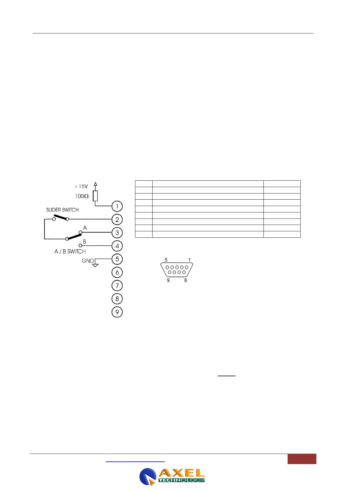
13.2 ‘START’ OPTIONAL REMOTE INTERFACE
Availabe on request, OX4-ST-START option adds latched Start/Stop control from slider on clean contacts.
With the slider at its „bottom‟ position pins 2 and 3 (with A input selected) are opened, while with the slider
arised the pins are closed. Two different pin closures are provided, depending on which input (A or B) is
selected.
A 15 VDC current-limited voltage is also provided for use with the remote control outputs.
13.2.1 INTERFACE PIN-OUT
Common Start / Stop connection
Start / Stop command while A input
Start / Stop command while B input
13.2.2 INTERFACE DESCRIPTION
Moving the slider away from the down position ( -infinite), a short-circuit will appear between Pins 2 and 3 or between
Pins 2 and 4, depending upon the selected Input source (A or B). Only one of the two Start commands (A or B) will be
therefore active at any time, depending upon the setting of the B SEL switch (see).
The short-circuit will last as long as the slider is „open‟ (thus always providing a „latched‟ command).
A + 15 VDC is supplied on Pin 1 via a 100 Ohm resistor.
Please, consider than max current allowed on Start/Stop circuit is 100 mA.
 Loading...