STEREO MODULE
ENG
Axel Technology srl www.axeltechnology.com STEREO MODULE
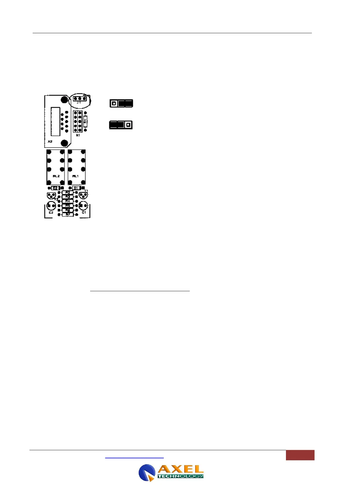
13.3.2 INTERFACE CONFIGURATION
The Start and Stop relays can be associated to the Input A or to the Input B. By default, they are associated to the Input
A. The Jumper J1, placed on the interface PCB (close to the rear panel), allows for alter the assignment, as shown in
the following picture:
Start and Stop commands associated to Input B
Start and Stop commands associated to Input A
13.3.1 INTERFACE DESCRIPTION
By moving the slider away from its down position (- inf), a momentary start (clean contact) will be issued between Pins 1
and 3 (see START Relay)
The slider closure always issues STOP pulse via the STOP relay (Pins 6 and 8).
See previous section for command assignment to Input A or Input B.
A + 15 VDC is supplied on Pin 1 via a 100 Ohm resistor.
Please, consider that max current allowed on Start/Stop relays is 500 mA at 24 Vdc.
 Loading...