8: Mixed Signal xNode • 36
© 2016 Axia Audio - Rev 2.0
Chapter Eight:
Mixed Signal xNode
The Mixed Signal xNode has one switched analog input (either microphone or analog stereo), two analog stereo inputs,
one AES/EBU input, three analog stereo outputs, one AES/EBU output, and 2 GPIO ports (5GPI/5GPO per port).
Rear Panel
The Mixed Sigal xNode uses RJ45 connectors for analog and AES audio, and an XLR connector for the selectable
Mic input.
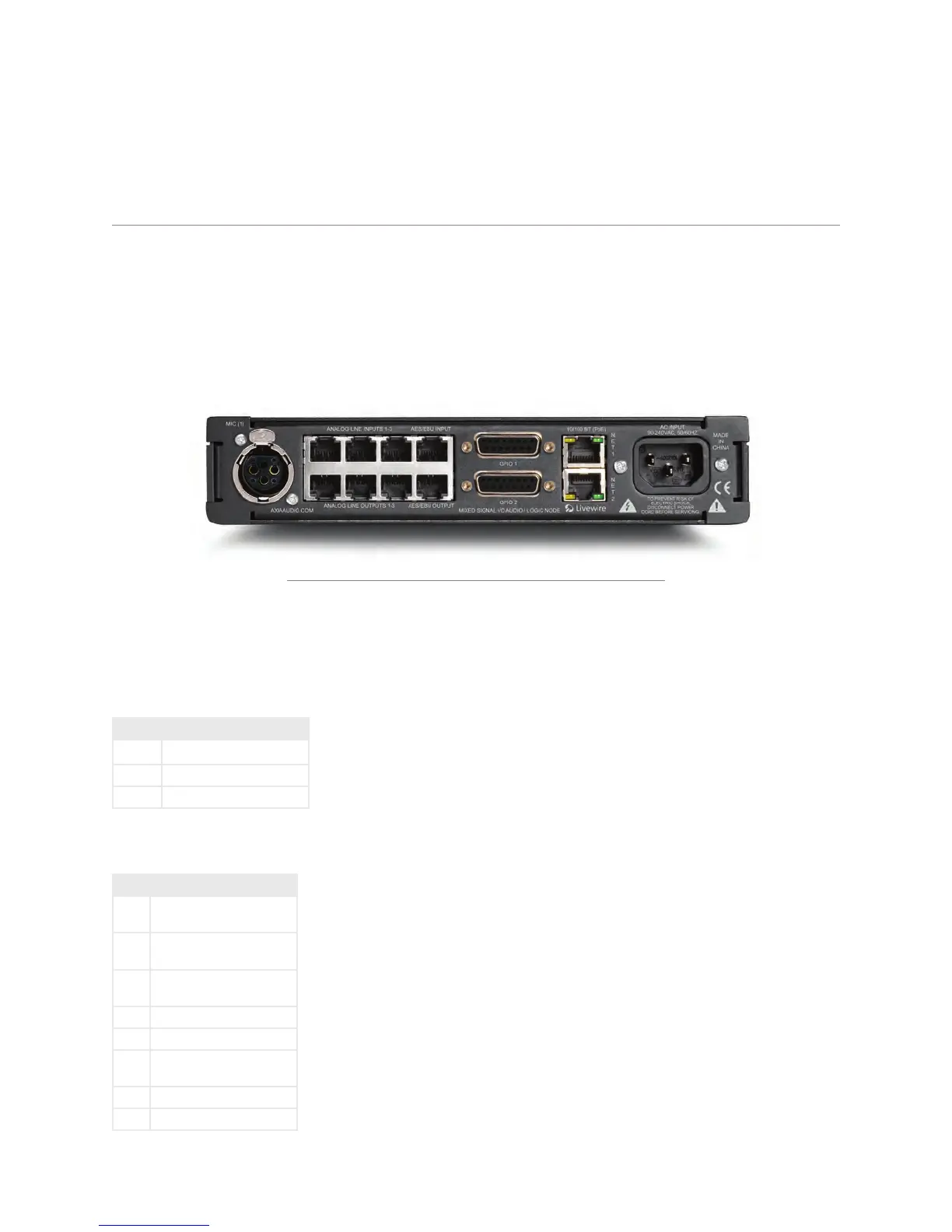
Figure 8-1: GPIO xNode Rear Panel
The top 4 RJ-45 style ports are inputs; three analog inputs followed by one AES/EBU input. The bottom 4 RJ-45
style ports are outputs; three analog outputs followed by one AES/EBU output.
The XLR-F connector is used as an analog input with the intention of it being a microphone input.
PIN FUNCTION
1 Shield
2 Positive
3 Negative
The pinout of an RJ-45 port
PIN FUNCTION
1 Left Channel /AES
Input/Output +
2 Left Channel /AES
Input/Output -
3 Right Channel
Input/Output +
4 Ground
5 Not Used
6 Right Channel
Input/Output -
7 Not Used
8 Not Used