A: GPIO Logic Table Samples • 43
© 2016 Axia Audio - Rev 2.0
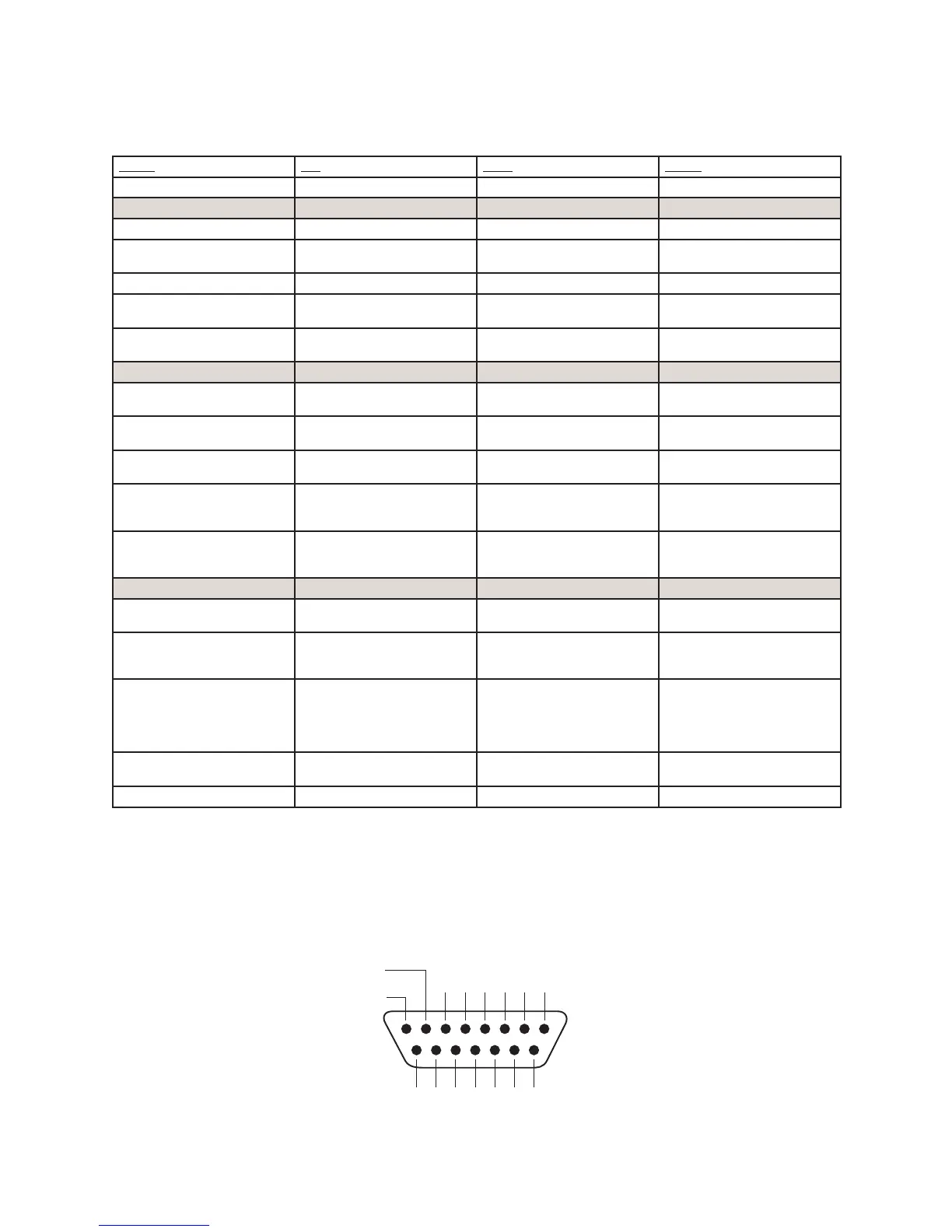
GPIO Line Input Logic
Name Pin Type Notes
INPUTS
ON Command 11 Active Low Input Turns channel ON
OFF Command 12 Active Low Input Turns channel OFF & sends
100 msec STOP pulse
PREVIEW Command 13 Active Low Input Turns preview ON
RESET Command 14 Active Low Input Turns channel OFF, while not
sending a STOP pulse
READY Command 15 Active Low Input Illuminates OFF lamp to indi-
cate source’s readiness
OUTPUTS
ON Lamp 1 Open Collector to Logic Com-
mon Return
Illuminates when channel is
ON
OFF Lamp 2 Open Collector to Logic Com-
mon Return
Illuminates when channel is
OFF and READY is active
PREVIEW Lamp 3 Open Collector to Logic Com-
mon Return
Illuminates when PREVIEW
is ON
START Pulse 4 Open Collector to Logic Com-
mon Return
A 100 msec pulse when the
channel status changes from
OFF to ON
STOP Pulse 5 Open Collector to Logic Com-
mon Return
A 100 msec pulse when the
channel status changes from
ON to OFF
POWER & COMMON
Source Common 7 Logic Common Connect to ground of source
device or to Pin 8
Logic Common 8 Internal 5 Volt return Can be connected to Pin 7
if source is not providing
common
Logic + 5 Volt supply 9 Logic Supply, Individually
Fused
Can be connected to Pin 10
if source is not providing
voltage; active only when
source has been assigned to
channel.
Source Supply 10 Common for all 5 inputs Connect to power supply of
source device or to Pin 9
NOT CONNECTED 6
8 7 6 5 4 3 2 1
15 14 13 12 11 10 9
ØV (GND)
SOURCE
OUTPUT
COMMON
RETURN
OUT
5
OUT
2
OUT
3
OUT
4
OUT
1N/C
IN
5
IN
4
IN
3
IN
2
IN
1
IN
COM
+5 V
POWER
GPIO v.”ZA” 4/2009