A: GPIO Logic Table Samples • 40
© 2016 Axia Audio - Rev 2.0
Appendix A:
GPIO Logic Table Samples
GPIO Operator’s Microphone Logic
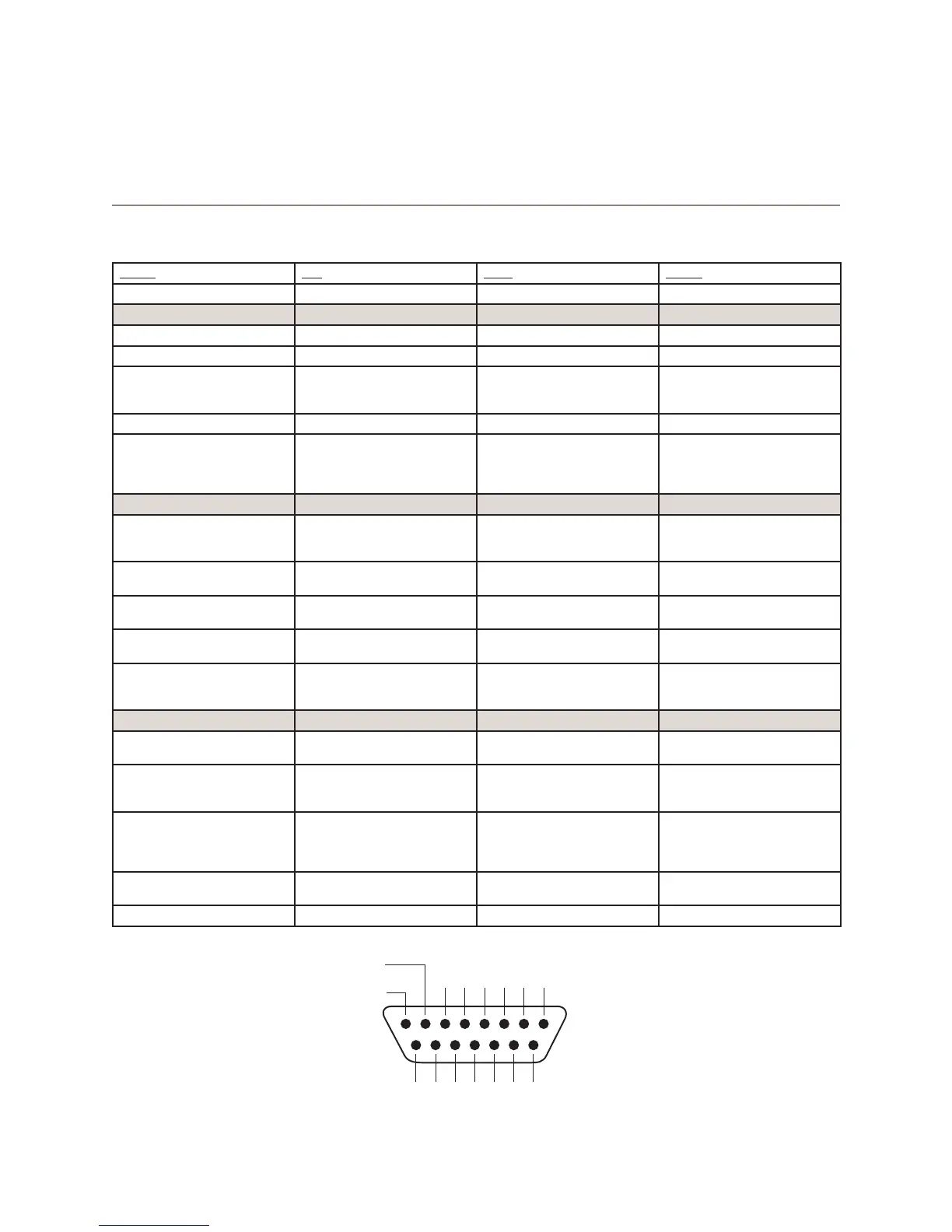
Name Pin Type Notes
INPUTS
ON Command 11 Active Low Input Turns channel ON
OFF Command 12 Active Low Input Turn channel OFF
TALK (to Monitor 2) Command 13 Active Low Input Activates the TALK TO MON2
function and routes mic audio
to the Talkback bus.
MUTE Command 14 Active Low Input Mutes channel outputs
TALK (to PREVIEWED
SOURCE) Command
15 Active Low Input Activates the TALK button
on every source currently in
preview and routes mic audio
to the Talkback bus.
OUTPUTS
ON Lamp 1 Open Collector to Logic Com-
mon Return
Illuminates when channel is
ON unless TALK or MUTE is
active
OFF Lamp 2 Open Collector to Logic Com-
mon Return
Illuminates when channel is
OFF
TALK (to Monitor 2) Lamp 3 Open Collector to Logic Com-
mon Return
Illuminates when TALK TO
MON2 is active
MUTE Lamp 4 Open Collector to Logic Com-
mon Return
Illuminates when MUTE is
active
TALK (to PREVIEWED
SOURCE) Lamp
5 Open Collector to Logic Com-
mon Return
Illuminates when TALK to
PREVIEWED SOURCE is
active.
POWER & COMMON
Source Common 7 Logic Common Connect to ground of source
device or to Pin 8
Logic Common 8 Internal 5 Volt return Can be connected to Pin 7
if source is not providing
common
Logic +5 Volt Supply 9 Logic Supply, Individually
Fused
Can be connected to Pin 10 if
source is not providing volt-
age; active only when source
has been assigned to channel.
Input Common 10 Common for all 5 inputs Connect to power supply of
source device or to Pin 9
NOT CONNECTED 6
8 7 6 5 4 3 2 1
15 14 13 12 11 10 9
ØV (GND)
SOURCE
OUTPUT
COMMON
RETURN
OUT
5
OUT
2
OUT
3
OUT
4
OUT
1N/C
IN
5
IN
4
IN
3
IN
2
IN
1
IN
COM
+
+5 V
POWER
SOURCE
GPIO v.”ZA” 4/2009