8: Mixed Signal xNode • 38
© 2016 Axia Audio - Rev 2.0
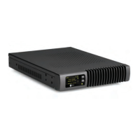
Take note to use current limiting resistors per the above chart if the voltage supplied is above 6vdc. The intention is
to limit the current to 20mA for each GPI pin. If the equipment being controlled is electrically isolated, than the use
of the GPIO port’s power supply is acceptable.
Figure 8-4
Axia GPIO accessory modules are designed to interface directly to the GPIO port. The DA-15 connector on the back
of an accessory module is a direct pin-to-pin match to the GPIO port of the xNode. Premade cables of this congura-
tion are commonly available through companies that specialize in interconnect cable assembly products.
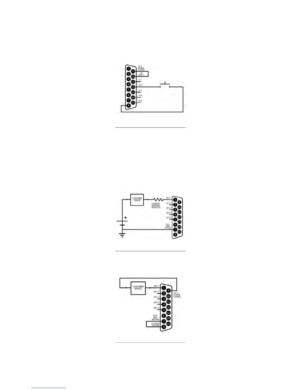
The GPO portion of the GPIO ports are solid state relays. Current should be limited to a combined 100 mA through
all the pins of a port. The following diagram shows the recommended connections for outputs with the use of an
external power supply.
Figure 8-5
If the device being controlled is electrically isolated, than the 5vDC supply can be used, maintaining a 100mA limit
on current drawn.
Figure 8-6