AXIS 233D Installation Guide Page 17
ENGLISH
ENGLISH
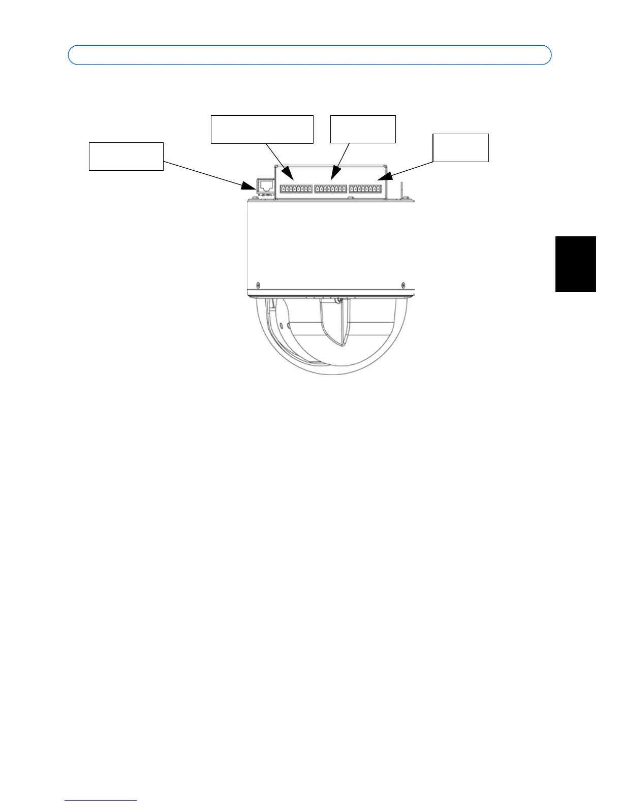
Unit connectors
Network connector - RJ-45 Ethernet connector. Using shielded cables is recommended. Use
care when inserting and removing the network cable.
I/O terminal connector - Used in applications for e.g. motion detection, event triggering,
time lapse recording, alarm notifications, etc. It provides the interface to:
• Power, auxiliary power, GND and audio.
• 4 solid state relay outputs - These can drive a maximum load of 50V DC at
500mA or they can drive heavier loads by connecting additional relay circuitry.
If the output is used with an external relay, a diode must be connected in parallel
with the load for protection against voltage transients. The terminals use a pho-
tocoupler and are electrically isolated from the other internal circuitry.
• 4 alarm inputs - Used for connecting external alarm devices and triggering
images for specific alarm-based events. The input is typically connected to a
motion detector or any other external security device, and images can be
uploaded whenever the detector is activated. The inputs are allowed 3.3 - 40VDC.
The terminals use a photocoupler and are electrically isolated from the other
internal circuitry.
Network
connector
Power/Audio
Outputs
Inputs