AXIS M7014
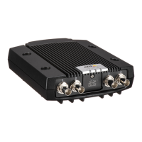
Hardware overview
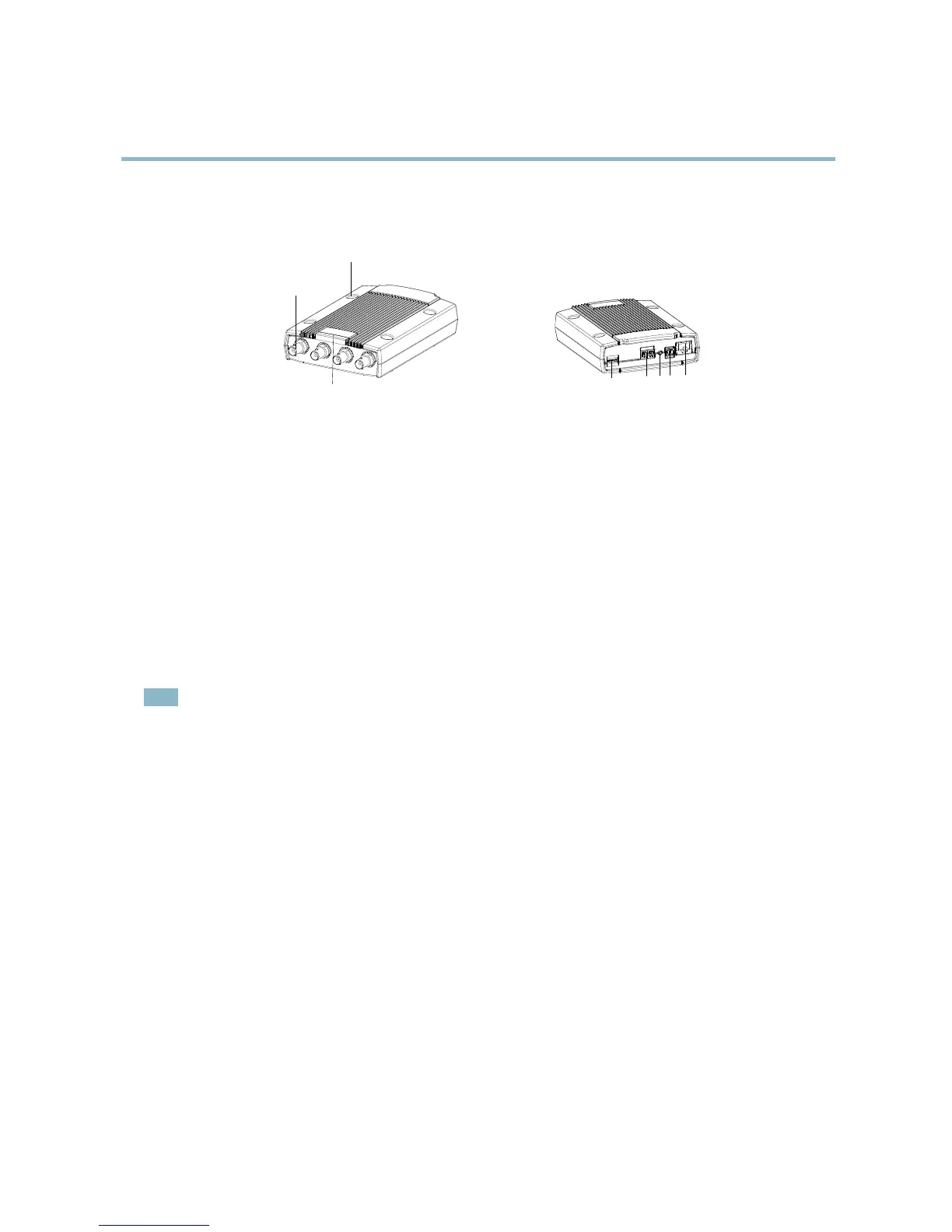
Hardware overview
1
2
3
4
5
6
7
8
1.
Mounting holes
2.
Video input connectors
3.
LED indicators for power, status and network
4.
SD memory card slot (microSD)
5.
RS-485/RS-422 connector
6.
Control button
7.
Power connector
8.
Nework connector (PoE)
Connectors
Network connector - RJ-45 Ethernet connector. Supports Power over Ethernet (PoE). A shielded network cable (STP) must be
used to protect the product against power surges.
SD card slot - A standard or high-capacity SD card (not included) can be used for l ocal recording with removable storage. For
instructions on how to insert and remove an SD card, please r efer to the Installation Guide.
Note
Before removal, the SD card s hould be unmounted to prevent corruption of recordings. To unmount the SD card, go to Setup
>SystemOptions>Storage>SDCardand click Unm ount.
Control button - The control button is used for:
• ConnectingtoanAXISVideoHostingSystemservice.Seepage 30. To connect, press and hold the button for about
1 second until the Status LED flashes green .
• ConnectingtoAXISInternetDynamicDNSService. Seepage 31. To connect, press and hold the button for
about 3 seconds.
• Resetting the product to factory default settings. See page 38.
Power connector - 2-pin terminal blo ck for power input.
4