AXIS Q1615-E Mk II Network Camera
Hardware Overview
• Digital input – An alarm input for connecting devices that can toggle between an open and closed circuit, for example:
PIRs, door/window contacts, glass break detectors, etc. When a signal is received the state changes and the input becomes
active (shown under System Options > Ports & Devices).
Note
The I/O connector is connected to the housing (fan/heater) on delivery. In the case of a fan or heater error, an input signal
will be triggered in the camera. Set up an action rule in the camera to congure which action the signal shall trigger. For
information about events and action rules, see Events on page 47.
Audio Connector
The Axis product has the following audio connectors:
• Audio in (pink) – 3.5 mm input for a mono microphone, or a line-in mono signal.
• Audio out (green) – 3.5 mm output for audio (line level) that can be connected to a public address (PA) system or an
active speaker with a built-in amplier. A stereo connector must be used for audio out.
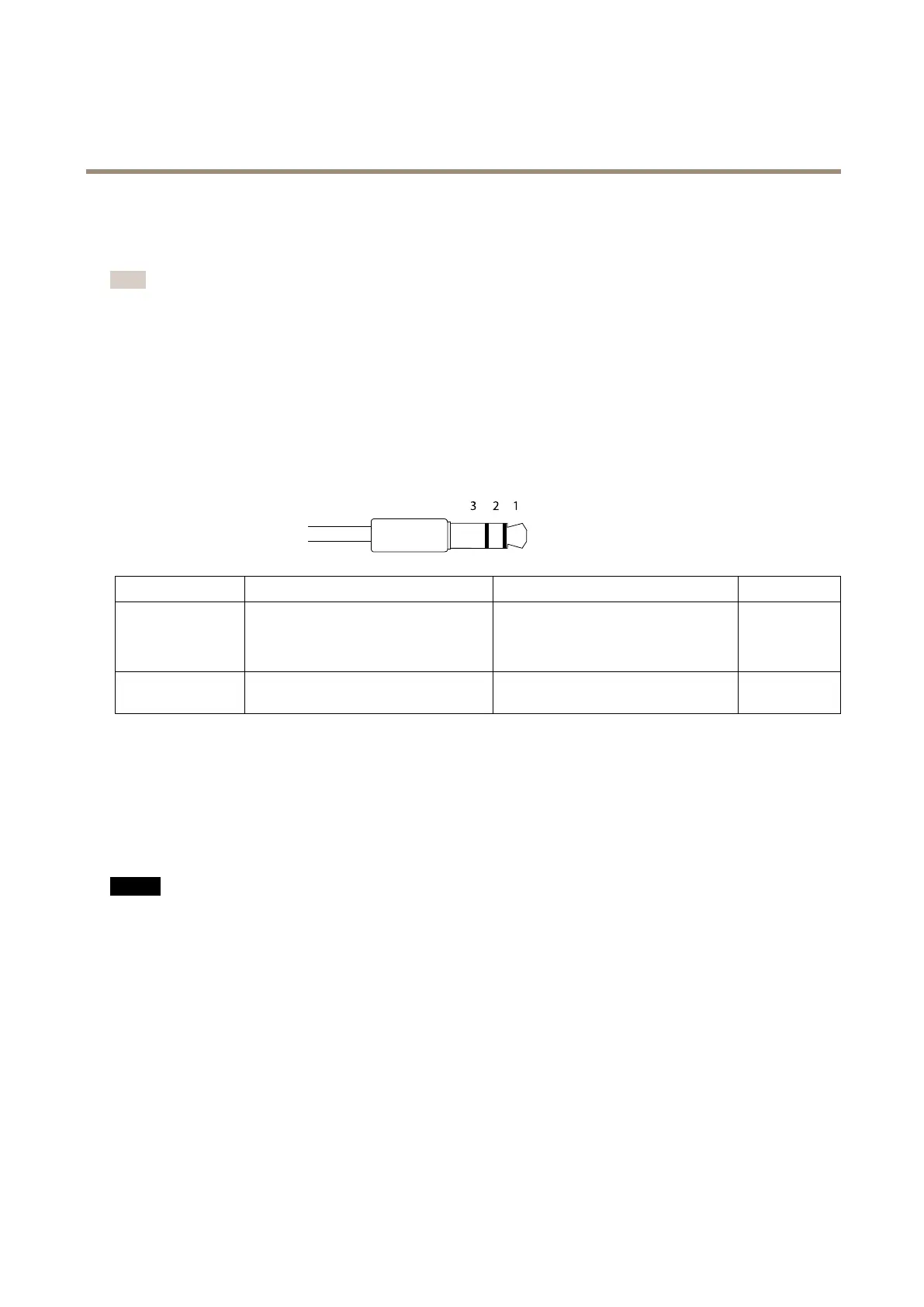
3.5 mm audio connectors
(stereo)
1 Tip 2 Ring
3 Sleeve
Audio Input
Balanced: ‘Hot’ signal Microphone/Line in
Unbalanced: Microphone/Line in
Balanced: ‘Cold’ signal Microphone/Line
in
Unbalanced: Unused
Ground
Audio Output
Line out, mono (stereo connector
compatible)
Line out, mono (stereo connector
compatible)
Ground
The internal microphone is used by default; the external microphone is used when connected. It is possible to disable the internal
microphone by connecting a plug to the microphone input.
RS485/RS422 Connector
Two terminal blocks for RS485/RS422 serial interface used to control auxiliary equipment such as pan-tilt devices.
SD card slot
NONO
NO
TICETICE
TICE
• Risk of damage to SD card. Do not use sharp tools, metal objects or excessive force when inserting or removing the
SD card. Use your ngers to insert and remove the card.
• Risk of data loss and corrupted recordings. Do not remove the SD card while the product is running. Disconnect power or
unmount the SD card from the Axis product’s webpages before removal.
This product supports microSD/microSDHC/microSDXC cards (not included).
For SD card recommendations, see www.axis.com
Control Button
For location of the control button, see Hardware Overview on page 6 .
The control button is used for:
• Resetting the product to factory default settings. See page 68.
9