21
AXOR Industries Service Manual MiniMagnum
TM
ver.1 rev.05/'15
2.6 Note about cable shielding
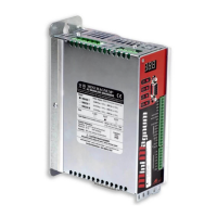
Remove the outside sheath
and afx the shield to the dedi-
cated retainer rings, by using
plastic clamps.
The conductor of the analogic signal must be twisted and shielded, and the shield must be connected
to ground as illustrated below:
Control signal cables
Motor cables
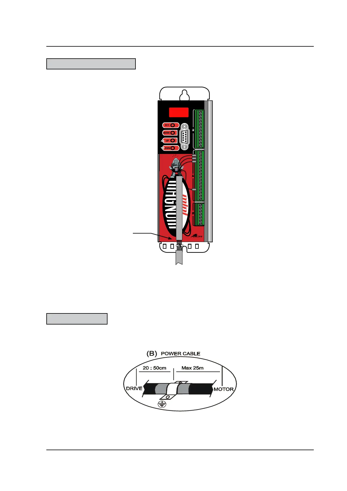
The shield of the motor cable (power and signal cables) are connected as follows:
• drive side (20:50cm) remove the outside sheath and x shield to the zinced pannel, by using
a u-clamp:
Note:
• To reduce the capacitive and inductive coupling, these cables must be run keeping a distance of more
than 30cm from the power cables (10 cm if they are shielded).
• If it is absolutely necessary to cross the control cables with the I/O's, do so at 90°, in order to reduce
the effect of the magnetic elds.
• motor side The shield is internally connected to the metal ring of the motor connector, thus to
earth through the motor's carcass.
 Loading...