32
AXOR Industries Service Manual MiniMagnum
TM
ver.1 rev.05/'15
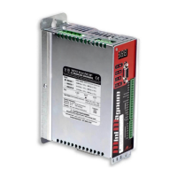
2.17 Pulse/Dir inputs connections
PULSE/DIRECTION MODE connection
1
2
CN
3
4
M3
+PULSE
-PULSE
+DIR
-DIR
MiniMagnum
TM
4k7
220
220
4k7
220
220
Logical signal 0/+5V
Note: We suggest connecting the shield on both sides: drive side, follow the indications illustrated on
paragraph 2.6.
OPTIONAL
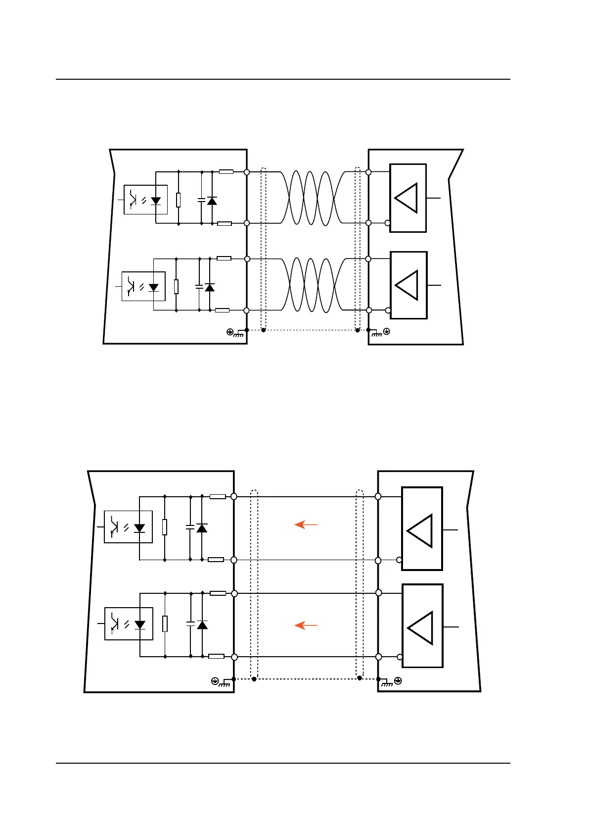
ELECTRICAL AXIS (GEARING) Connection
1
2
MiniMagnum
(Slave)
3
4
M3
A+
A-
B+
B-
MiniMagnum
TM
(Master)
M2
1
2
3
4
4k7
220
220
4k7
220
220
Note: We suggest connecting the shield on both sides: drive side, follow the indications illustrated on
paragraph 2.6.
OPTIONAL
 Loading...