29
AXOR Industries Service Manual MiniMagnum
TM
ver.1 rev.05/'15
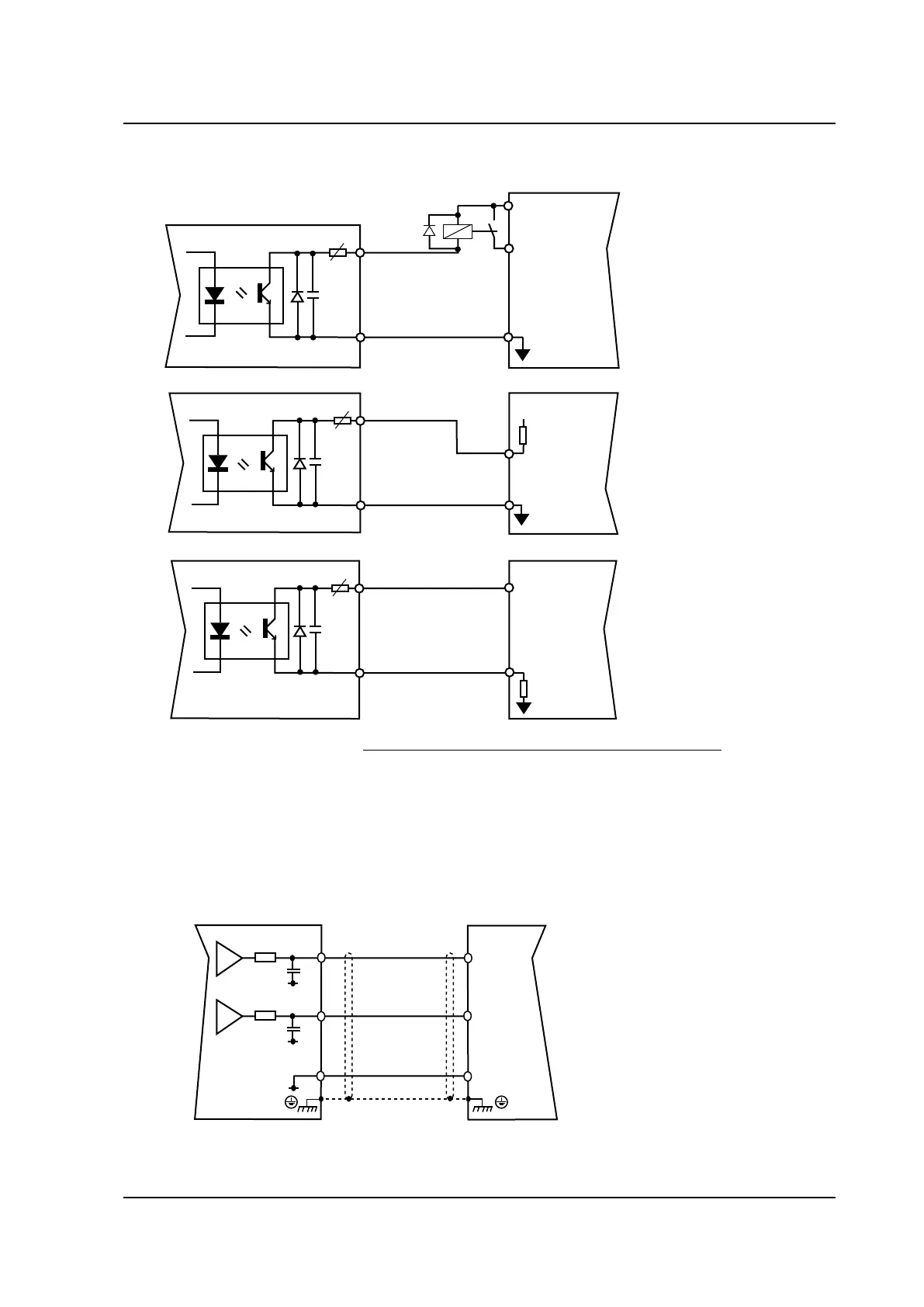
2.14 Analog and digital outputs connections
DIGITAL OUTPUT Connection (example)
ANALOG OUTPUTS Connections
MiniMagnum
CN
ANALOG1
CN-GND
5
7
180
470n
ANALOG2
6
180
470n
AN-OUT1
AN-OUT2
M1
AGND
+24VDC
refered to I/O GND
I/O GND
13
14
CN
I/O GND
LOAD
IN1-DIGITAL
CN
25R
LOAD
M1
25R
M1
25R
M1
+24VDC
refered to I/O GND
13
14
13
14
MiniMagnum
TM
MiniMagnum
TM
MiniMagnum
TM
+24VDC
refered to I/O GND
This digital output can be used to send messages from the pre-programmed function of the drive.
For a detailed description of the pre-programmed functions see enclosure "Speeder One Interface"
on the CD provided with the drive.
If there is the M3 connector (OPTIONAL), it provides an additional digital output.
Max. load for each output:
50[mA].
Always use a relay with a diode
in parallel.
They permit visualisation by oscillo-
scope of some of the drive’s meas-
urement values.
The two outputs furnish +/-10Volt
as the low scale setting refers to.
They can be set by the Speeder One
interface.
Note: We suggest to connect the shield on both sides: drive side follow the indications illustrated on
paragraph 2.6.
 Loading...