28
AXOR Industries Service Manual MiniMagnum
TM
ver.1 rev.05/'15
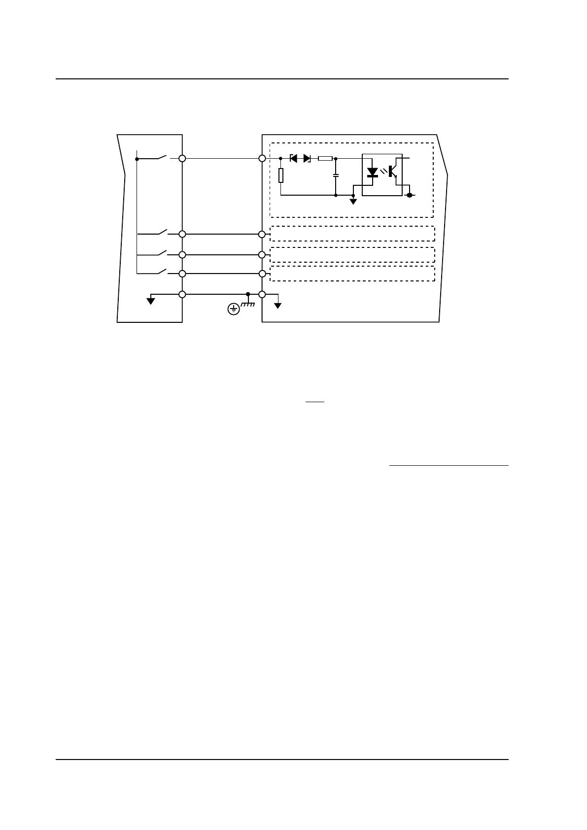
2.13 Digital inputs connection
DIGITAL INPUTS connection
DGT- IN RTN
I/O GND
DGT-IN1
(ENABLE)
+24VDC
refered to I/O GND
CN
MiniMagnum
TM
M1
8
9
10
11
12
DGT-IN2
DGT-IN3
DGT-IN4
10k
DGT-IN RTN
5V1
DGND
Note:
• The enable signal should be +24VDC-7mA (PLC compatible). The enable range is between +14V
Min and +30V Max.
• The M1-8 terminal (DGT-IN1 (ENABLE)) is used only as the drive’s enable. If M1-8 is HIGH
(+24VDC) the drive is enabled (without active alarms and if start up sequence, illustrated on para-
graph 2.21, is respected); if M1-8 is LOW (0V), the motor is without torque.
ATTENTION: THE DRIVE'S ENABLE/DISABLE, BY USING THE ENABLE INPUT, IS NOT CONSIDERED A
SECURITY FUNCTION.
• The M1-9, M1-10, M1-11 programmable inputs can be used to activate pre-programmed functions
of the drive (for example: limit switch , electromechanical brake, homing and positioning procedures,
emergency stop, etc.).
For a detailed description of the pre-programmed functions see enclosure "Speeder One Interface",
"Additional Features Manual" and "Positioner Manual" on the CD provided with the drive.
If there is the M3 connector (OPTIONAL), it provides ve additional digital inputs and one of them is
programmable (M3-7).
• Connect pin M1-12 (DGT-IN RTN) to the ground bar of the system.
 Loading...