24
AXOR Industries Service Manual MiniMagnum
TM
ver.1 rev.05/'15
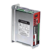
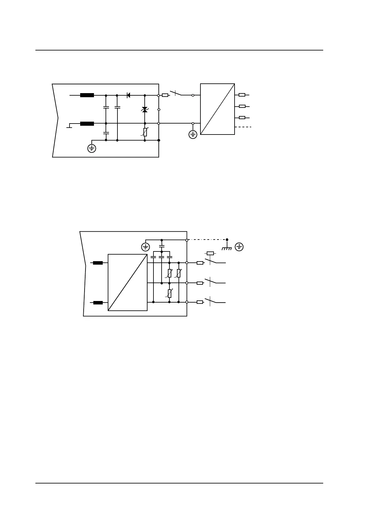
2.9 Supply connections
+24V
0V
L
L
DC
AC
3
1
PE
+24V
0V
F
3
2
F
2
F
2
F
2
3PH
50/60Hz
230...480Vac
MiniMagnum
TM
M4
L1
L2
L3
AUXILIARY SUPPLY +24Vdc
Note:
• Always insert a power relay or a thermal magnet on every phase of the products power
supply.
• If a power supply between 380V and 480V is utilized and ground protection is not present, or there
is an asymmetrical grounding system, an isolation transformer is required.
The nominal power of the transformer is calculated by adding the various wattage of each mo-
tor:
Pt = Pn+Pn+Pn+...
Pt= nominal power of the transformer (VA)
Pn= nominal power of each motor (VA), which can be calculated in this way:
Pn = n x Cn / 9,55
Pn=nominal motor power (W)
n= motor speed (rpm)
Cn= motor nominal torque (Nm)
• For single phase power supply use L1 and L2.
AC
DC
1
2
3
4
PE
F
2
L1
L2
L3
M5
MiniMagnum
3/PE
50/60Hz
110...480Vac
F
2
F
2
POWER SUPPLY
Note:
• Accepted voltage: +24VDC (0%/+15%);
• current required for the external supply: 3A (motor with brake);
• current required for the external supply: 1A (motor without brake);
• we suggest to insert the F
3
(6A T) fuse;
• Remember to connect the 0V of the external supply to the ground bar.
External supply
+24VDC
 Loading...