AXOR Industries Service Manual MiniMagnum
TM
ver.1 rev.05/'15
42
3.1 Display
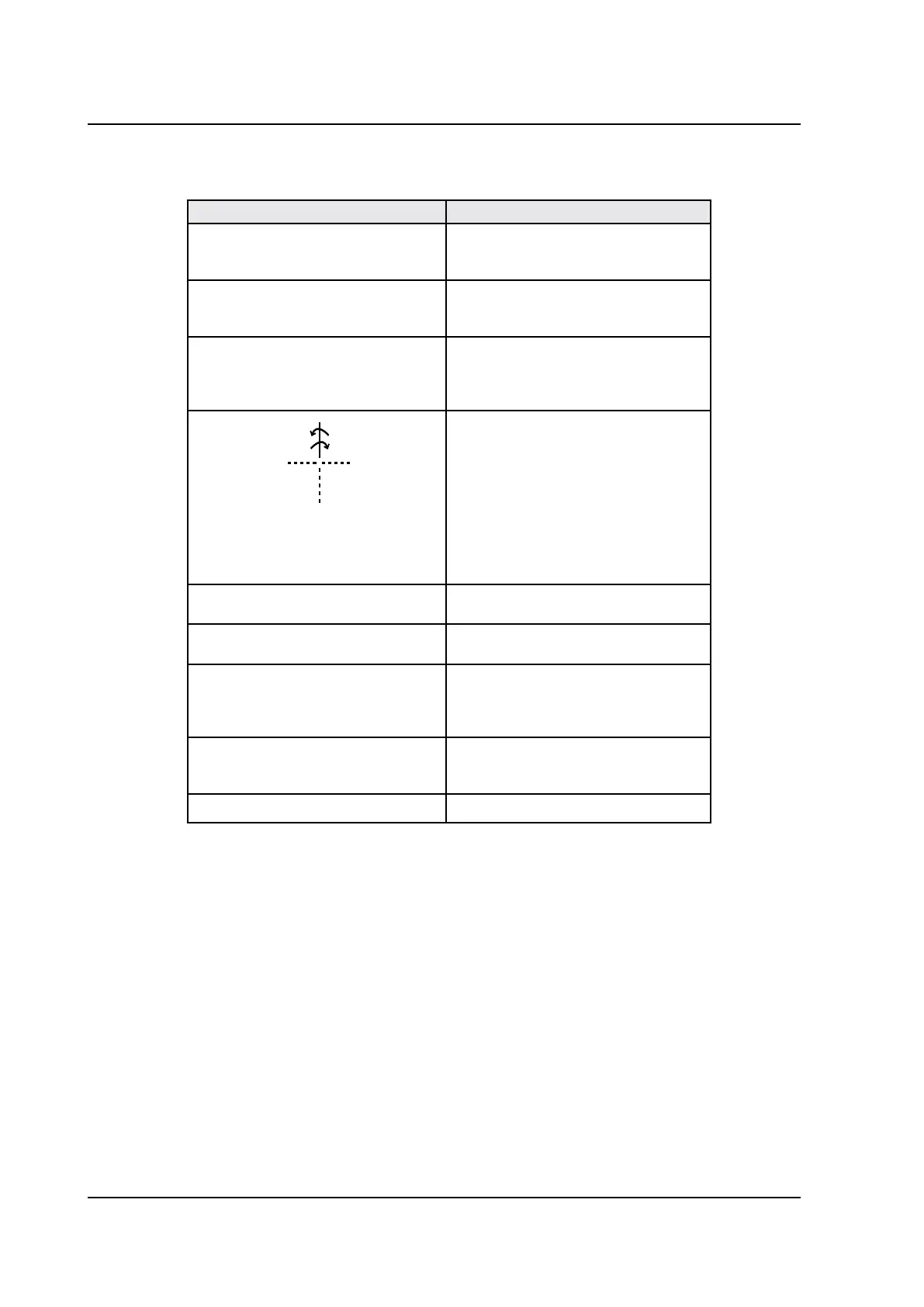
A display LED visualises: the drive's status, the inserted values, the alarms.
Symbol Description
F
The digital input ENABLE is enabled,
while the digital input set with the
"Ref on" function is disabled.
E
The digital input ENABLE is disa-
bled, while the digital input set with
the "Ref on" function is enabled.
[ ]
The digital input ENABLE and the
digital input set with the "Ref on"
function are both enabled; the mo-
tor does not move.
(segment appears rotating in a
clockwise or counter-clockwise
direction)
The rotor is turning in a clockwise
or counter-clockwise direction.
0ı
This appears when the negative lim-
it switch (NSTOP) is interrupted.
0 ı
This appears when the positive limit
switch (PSTOP) is interrupted.
- - -
This appears when the converter
is correctly powered on, the digital
input ENABLE is disabled and there
are no alarms.
24 UP
This appears when there is the
+24VDC auxiliary supply, but not
the main supply.
ALxx
There is alarm xx.
 Loading...