34
AXOR Industries Service Manual MiniMagnum
TM
ver.1 rev.05/'15
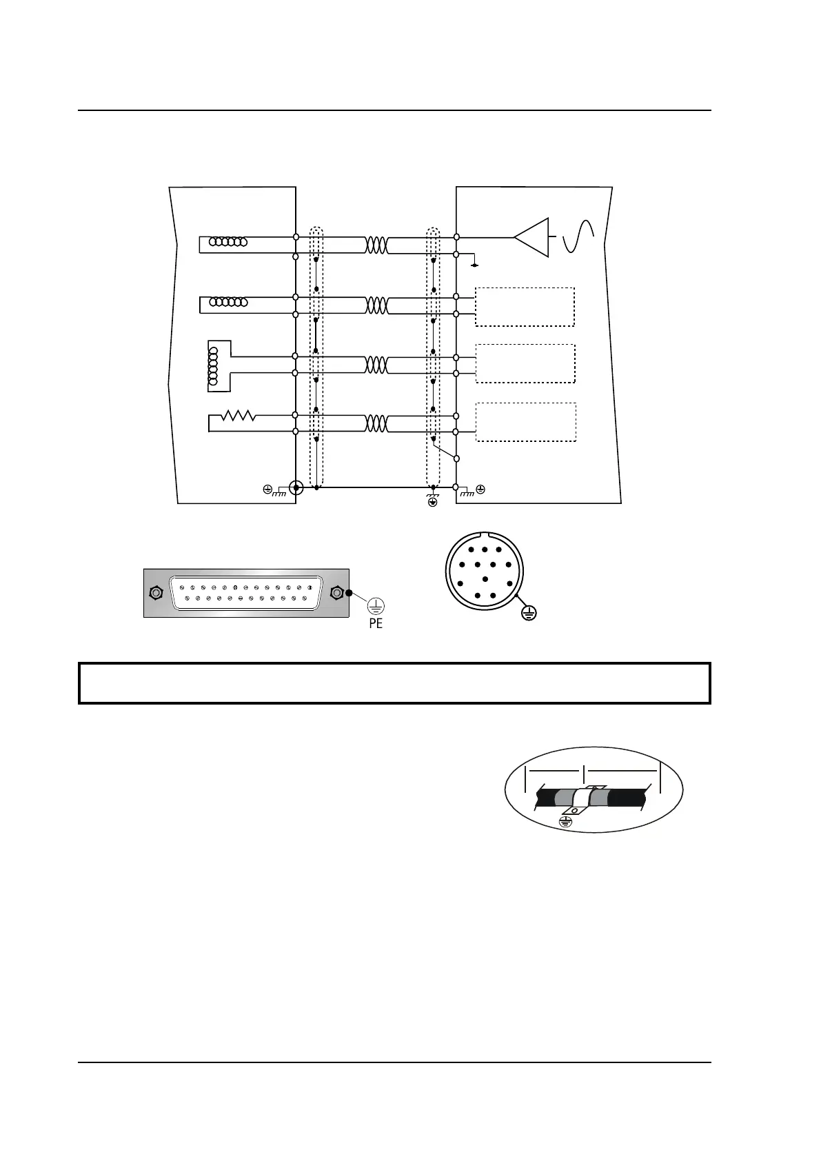
2.18 Feedback signals connections
SIN INPUT
COS INPUT
PTC INPUT
PTC MOTOR
4V RMS
25
16
23
14
24
15
4
17
8
13
+ECC
-ECC
+SEN
-SEN
+COS
-COS
Drive side
Motor side
RESOLVER
J1
5
9
3
7
4
8
2
6
AGND
Motor Cable
Drive
Motor
20:50cm
Max 25m
12 pole connector
(Resolver)
1
9
8
2
10
12
7
3
11
6
4
5
PE
*
1 2 3 4 5 6 7 8 9 10 11 12 13
14 15 16 17 18 19 20 21 22 23 24 25
J1 connector
Sub-D 25 pole
OPTIONAL
RESOLVER FEEDBACK connection
If the motor does not have thermal protection (PTC MOTOR) you should bridge pins 4
and 17 on the "J1, Sub-D 25 pole" connector of the drive.
Note: The ground connection of the external shield must
be made on the zinc-coated panel (using a u-clamp) near the
drive (20-50cm).
Motor side: the shield is connected to connector's metal
ring.
 Loading...