7
AXOR Industries Service Manual MiniMagnum
TM
ver.1 rev.05/'15
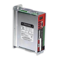
1.1 Description
DIGITAL INPUTS/OUTPUTS
9 DIGITAL INPUTS
They are programmable for: the limit switch, the holding
brake, the homing and positioning procedures, the emer-
gency stop, the reset alarm, etc.
4 standard
+
5 optional
2 programmable
DIGITAL OUTPUTS
They can be used to send messages from pre-programmed
functions of the drive.
1 standard
+
1 optional
EMULATED ENCODER
OUTPUTS
There are 6 pins dedicated to emulated encoder with
different programmed ratios (1/2, 1/4, 1/8, 1/16, 1/32,
1/64, 1/128) between output pulse/rev and encoder/
resolver ones.
standard
ANALOG INPUTS/OUTPUTS
1 ANALOG
COMMON MODE
INPUT (TPRC)
It is used for controlling the current from the drive. standard
1 ANALOG
DIFFERENTIAL or
COMMON MODE
INPUTS (+/-Vref)
It is used for piloting the drive with an analogue speed
reference from an external controller.
standard
2 programmable
ANALOG OUTPUTS
They allow you to visualise by the oscilloscope some of the
drive’s measurement values (for example: the velocity, the
Iq current, etc.)
standard
GENERAL FEATURES
KEYPAD
Four buttons (UP-DW-MODE-SET) allow the manual
insertion of data without using a PC.
standard
DISPLAY
A display with 3 characters visualises: the inserted
values, the drive’s status, the alarms.
standard
SPEEDER ONE
SOFTWARE
INTERFACE
The Axor Speeder One interface allows you to set and man-
age all drive’s parameters.
It uses a PC connected to the drive and the communication
between the drive and PC is done by a RS232 cable using
the ModBUS protocol.
The software works on the following operating systems:
Windows 98, Windows 2000, Windows XP.
standard
 Loading...