5-71
Chapter 5. DETAILED DESCRIPTION OF EACH FUNCTION
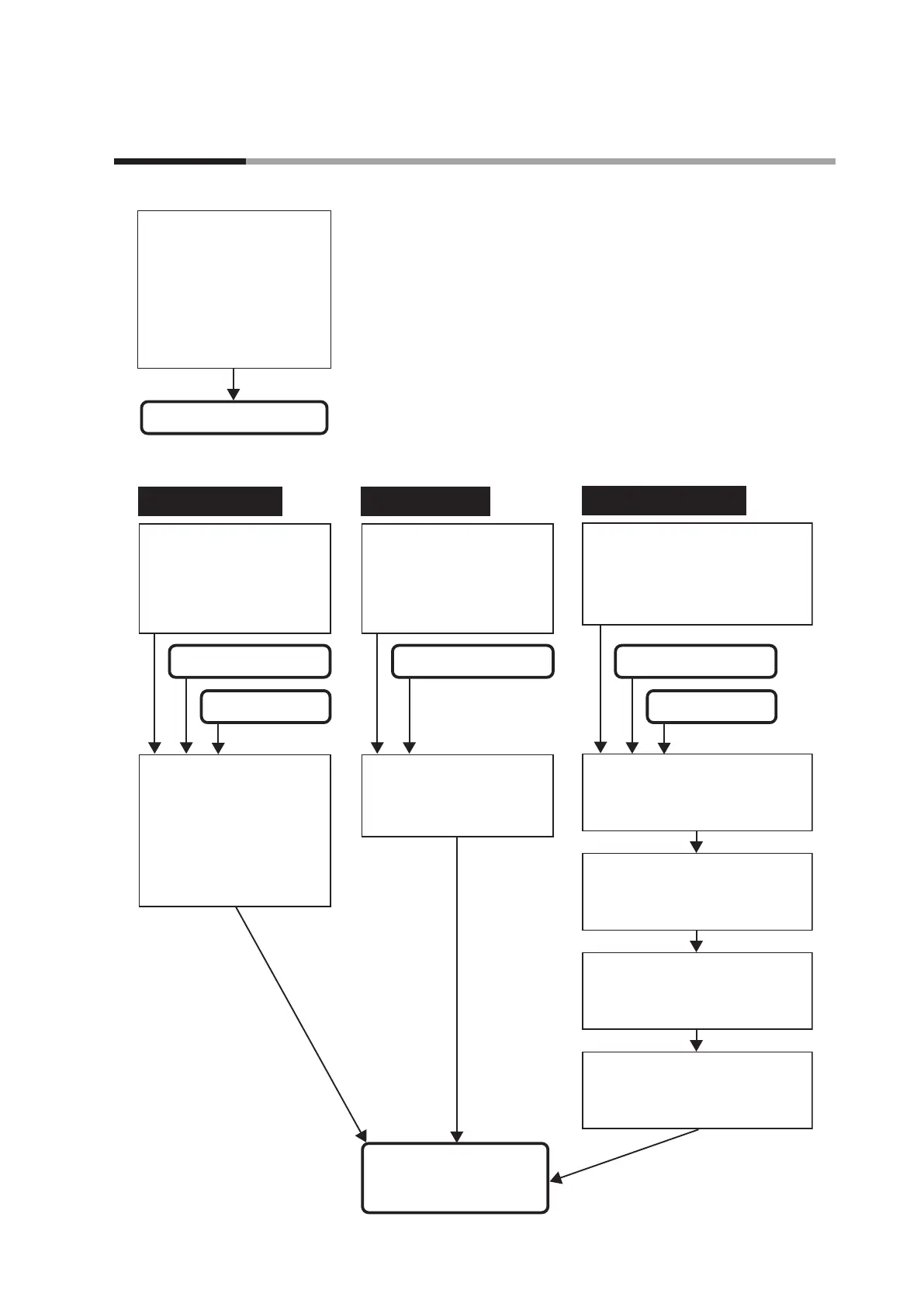
The following shows the functional block diagram of the digital output (DO):
MV1 and MV2
control output status
Control outputs 1 to 2
Event outputs 1 to 3
Output assignment is used.
MV1 and MV2
control output status
Default output is used.
MV1 and MV2
control output status
Internal Event status
MV1 and MV2
control output status
Internal Event status
Control output is used.
MV1 process: ON/OFF control output,
time proportional output, and
time proportional output (heat)
of Heat/Cool control.
MV2 process: Time proportional
output (cool) of Heat/Cool control
(Setting: Parameters
CyU, Cy, CyU2, Cy2, tp.ty)
Default output
(Setting: DO Assignment Ot 1. 1,
Ot2. 1, EV 1. 1 to EV3. 1 must be
set at [Default output].)
Control output
(Setting: DO Assignment Ot 1. 1,
Ot2. 1, EV 1. 1 to EV3. 1 must be
set at [MV1] or [MV2].)
Output assignment
(Setting: DO Assignment Ot 1. 1,
Ot2. 1, EV 1. 1 to EV3. 1 must be set
at [Output assignment result].)
Output process from each DO
(terminal)
Control output: MV1
Control output: MV2
Event output 1: Internal Event 1
Event output 2: Internal Event 2
Event output 3: Internal Event 3
Output process from each DO
(terminal)
(Setting: DO Assignment Ot 1. 1,
Ot2. 1, EV 1. 1, EV2. 1, EV3. 1)
Output assignment and polarity
(Setting: DO Assignment, Output
assignment A to D Ot 1.2 to Ot2.6,
Ev 1.2 to Ev3.6)
Output bit function, Function 1 to 4
(Setting: DO Assignment Operation
type Ot 1. 1 to Ot2. 1, Ev 1. 1 to Ev3. 1)
Polarity of output bit function
(Setting: DO Assignment Polarity
Ot 1.7 to Ot2.7, Ev 1.7 to Ev3.7)
Output latch
(Setting: DO Assignment Latch
Ot 1.8 to Ot2.8, Ev 1.8 to Ev3.8)
5 - 9 Digital Output (DO)