5-51
Chapter 5. DETAILED DESCRIPTION OF EACH FUNCTION
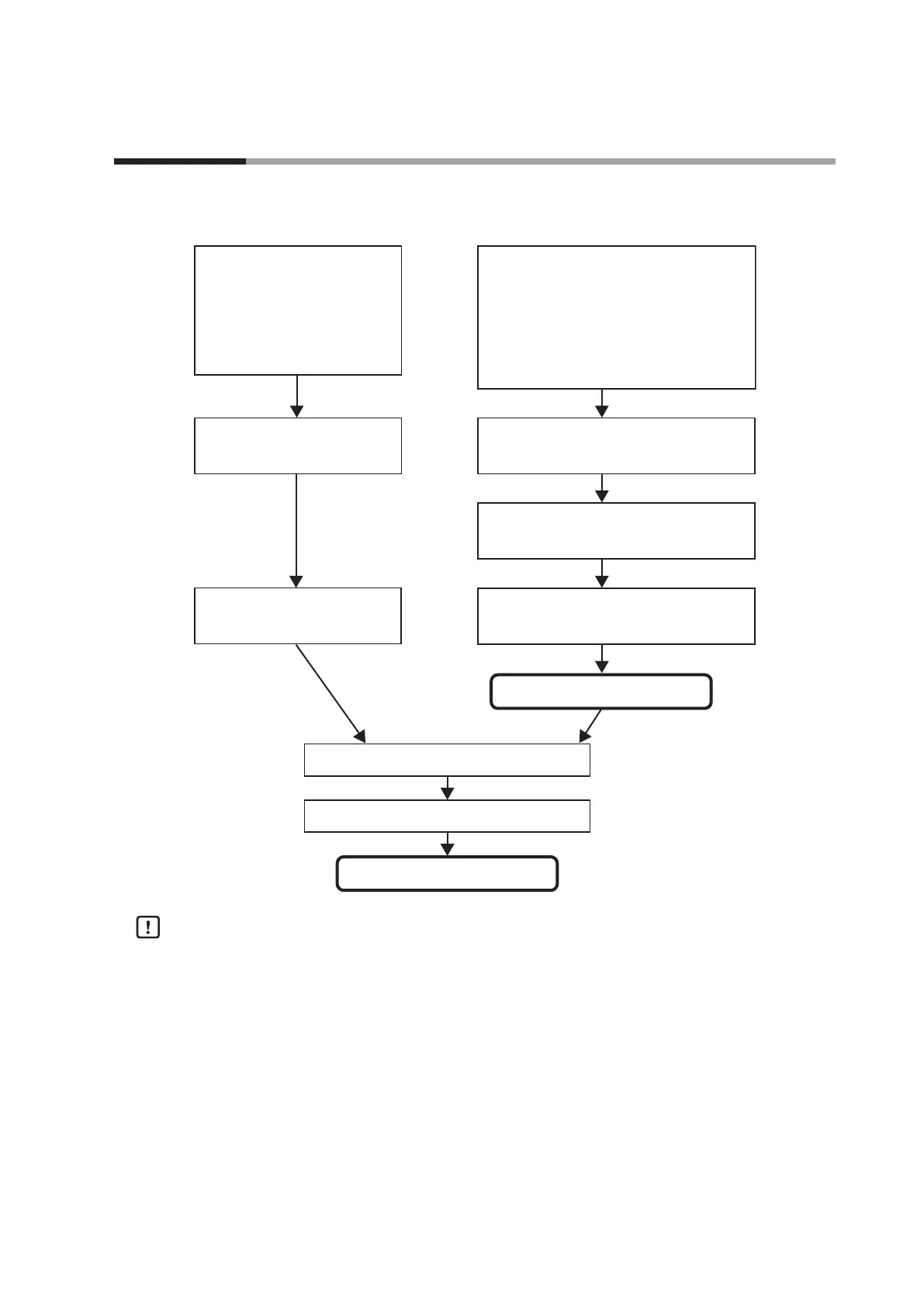
The following shows the functional block diagram of the digital input (DI) and internal contact:
Input bit function is not used.
(Setting: [Input bit function
is not used.]
must be set using DI Assignment
di 1.2 to di 5.2.)
DI status (ON/OFF)
Input assignment Polarity
(Setting: DI Assignment Polarity A to D di 1.7
to di 5.7)
Internal Contact Input bit function result
Input bit function is not used.
Input assignment
(Setting: DI Assignment Input assignment A di 1.3
to di 5.3,
DI Assignment Input assignment B di 1.4 to di 5.4,
DI Assignment Input assignment C di 1.5 to di 5.6,
DI Assignment Input assignment D di 1.6 to di 5.6)
Input bit function 1 to 4
(Setting: DI Assignment Input bit function di
1.2
to di
5.2)
Input bit function Polarity
(Setting: DI Assignment di 1.8 to di 5.8)
Input bit function is used.
Event channel denitions
(Setting: DI Assignment di 1.9 to di 5.9)
Operation type (Setting: DI Assignment di 1. 1
to di 5. 1)
Internal contact function
Polarity
(Setting: DI Assignment di
1.8 to di
5.8)
Handling Precautions
Even though five internal contacts 1 to 5 are provided, the number of digital
inputs determined by the optional model is 0 to 4 points.
With the default settings before shipment, the operations of digital input 1 to 4
have already been connected to internal contacts 1 to 4.
To utilize the operation of internal contact 5, it is absolutely necessary to set the
DI Assignment.
5 - 7 Digital Input (DI) and Internal Contact