10-2
Chapter 10. MAINTENANCE AND TROUBLESHOOTING
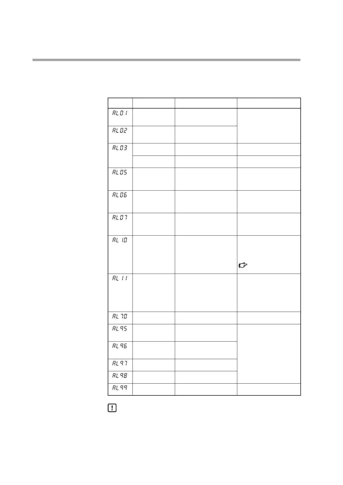
Alarm displays and corrective action
The following table shows the alarm displays and corrective actions if any failure
occurs in this unit:
Alarm code
Failure name Cause Corrective action
PV input failure
(Over-range)
Sensor burnout, incorrect
wiring, incorrect PV input
type setting
Check the wiring.
Set the PV input type again.
PV input failure
(Under-range)
Sensor burnout, incorrect
wiring, incorrect PV input
type setting
CJ failure Terminal temperature is
faulty (thermocouple).
Check the ambient
temperature.
PV input failure Sensor burnout, incorrect
wiring (RTD)
Check the wiring.
RSP input failure
(Over-range)
(Displayed only in
the RSP mode.)
Sensor burnout, incorrect
wiring, incorrect RSP input
type setting
Check the wiring.
Set the RSP input type again.
RSP input failure
(Under-range)
(Displayed only in
the RSP mode.)
Sensor burnout, incorrect
wiring, incorrect RSP input
type setting
Check the wiring.
Set the RSP input type again.
MFB input failure Burnout, incorrect wiring Check the wiring.
Check the MFB input value.
Check the settings for
C6
1
and
62
in the setup bank.
Motor adjustment
failure
Check for burnout or
incorrect wiring.
Motor power shutdown.
Readjust the motor after
checking the wiring and
motor power.
Check the settings for
C6
1
and
62
in the setup bank.
p.5-109 (for details on
AL
10
)
CT input failure
(over-range)
(CT input 1 or 2, or
both)
A current exceeding the
upper limit of the display
range was measured. The
number of CT turns or the
number of CT power wire
loops is incorrectly set, or
wiring is incorrect.
Use a CT with the correct
number of turns for the
display range, reset the
number of CT turns, reset
the number of CT power
wire loops, and/or check the
wiring.
A/D conversion
failure
A/D converter is faulty. Replace the unit.
Parameter failure Data is corrupted by noise,
or power is shut-down while
the data is being set.
• Restart the unit.
• Set the data again (set
data for
AL95
/
97
and
adjustment data for
AL96
/
98
).
• Replace the unit.
Adjustment data
failure
Data is corrupted by noise,
or power is shut-down while
the data is being set.
Parameter failure
(RAM area)
Data is corrupted by noise.
Adjustment data
failure (RAM area)
Data is corrupted by noise.
ROM failure ROM (memory) is faulty. • Restart the unit.
• Replace the unit.
Handling Precautions
• If ROM version 1 of the instrument information bank (
I
d02
) is prior to
2.04, CT input failure (
AL
1
1
) is not displayed.
• If
AL07
and
AL
10
are displayed alternately, take corrective actions for
AL
10
first.
• This device will not recover from
AL07
and
AL
10
by restarting it.
Corrective actions are described in the above table.