METER GASKETS AND GROUNDING
Gasket and grounding requirements must be considered when determining the meter location, orientation and application.
Meter/Pipeline Connection Gaskets
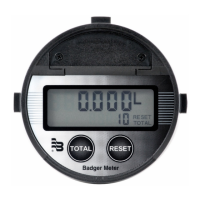
You must install gaskets (not provided) between the detector's
isolating liner and the pipeline flange to ensure a proper and secure
hydraulic seal. Use gaskets that are compatible with the fluid. Center
each gasket on the flange to avoid flow restrictions or turbulence in
the line.
During installation, do not use graphite or any electrically conductive
sealing compound to hold the gaskets. This could compromise the
accuracy of the measuring signal.
If you are using a grounding ring in the detector/pipeline connection,
place the ring between two gaskets. (See "Non-Conductive Pipe
Grounding" on page 12.)
Figure 15: Meter/Pipeline Connection Gaskets
Meter Grounding
Process pipeline material can be either electrically conductive (metal) or not electrically conductive (made of or lined with
PVC, fiberglass or concrete).
MPORTANTI
It is essential that the mag meter amplifier’s input ground (zero voltage reference) be electrically connected to the liquid media and
to a good, solid earth ground reference.
Conductive Pipe Grounding
To achieve an adequate ground, the meter body MUST be electrically connected to the liquid media. The mag meter flanges
are provided with grounding bolts for this purpose.
If the pipe material is electrically conductive, simply install grounding straps between these grounding bolts and the
mating flanges.
To ensure a good electrical connection at the mating flanges, we recommend that you drill and tap the flanges and install a
grounding screw (not provided).
These grounding straps must be copper wire, at least 12 AWG size. They must be connected on both sides (inlet and outlet) of
the detector and to a local, earth ground.
Non-Conductive Pipe Grounding
MPORTANTI
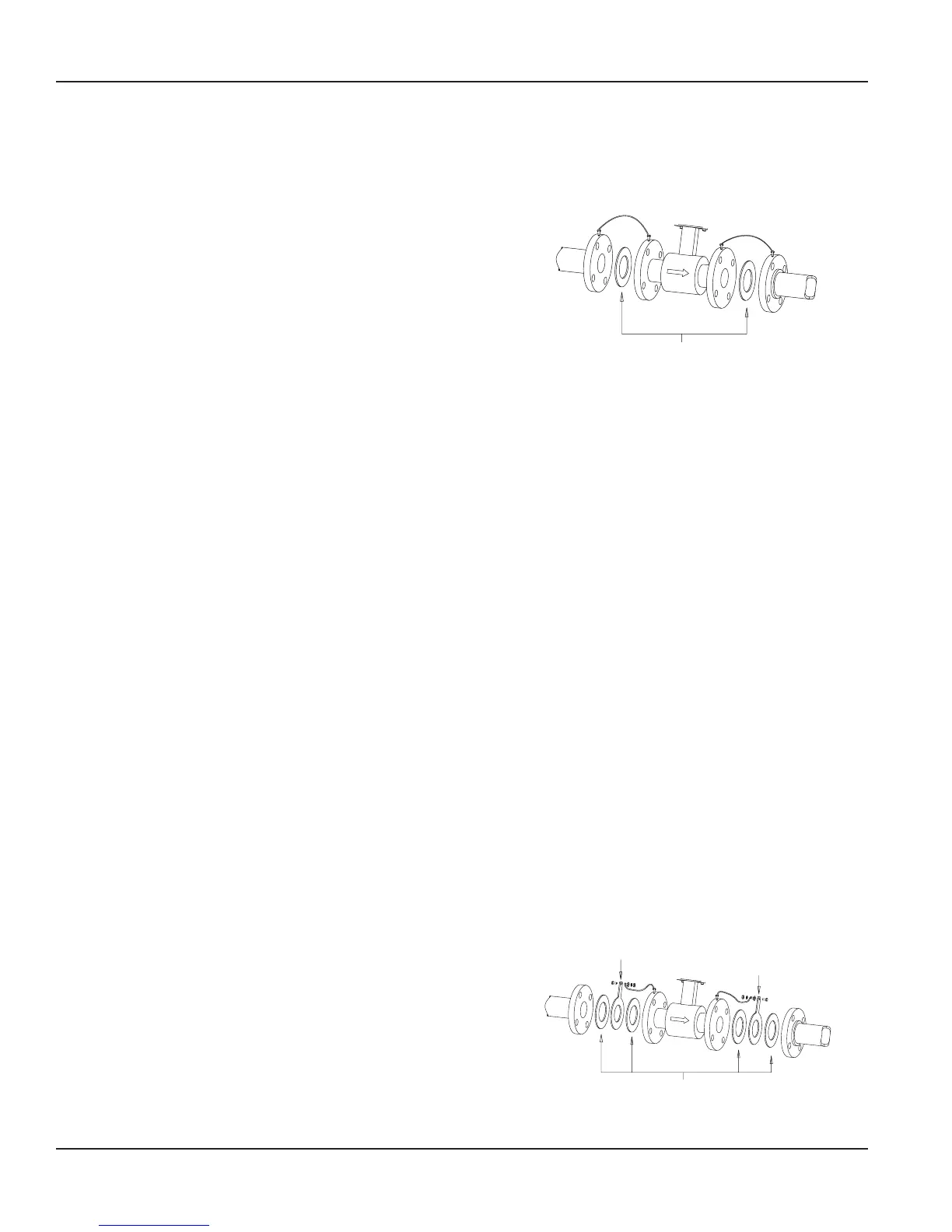
If the process pipe is not electrically conductive (PVC, fiberglass, cement-lined pipes or any other non-conductive material) and the
meter was not originally ordered with an optional grounding electrode, you must install a pair of grounding rings between the
mating flanges at both ends of the meter. See the following illustration.
In this case, the grounding straps should be connected to both of the
grounding rings and to a good, solid earth ground. Grounding rings
are available in stainless steel. If your fluid is too aggressive for stainless
steel, order a meter with the optional grounding electrode in a material
compatible with the fluid.
GROUNDING RING
GROUNDING RING
Figure 16: Non-Conductive Pipe Grounding
M-Series® M5000 Electromagnetic Flow Meter
Page 12 September 2013
| sales@mvandc.com | Phone: 877.566.3837 | Fax: 925.407.2903