CONFIGURING INPUT/OUTPUT (I/O)
This section describes wiring the following M5000 outputs:
• Digital outputs
• Communication
When the sensor and the amplifier have been wired, wire any outputs to the M5000 amplifier.
Follow all of the safety precautions and local code to prevent electrical shock and damage to the electronic components.
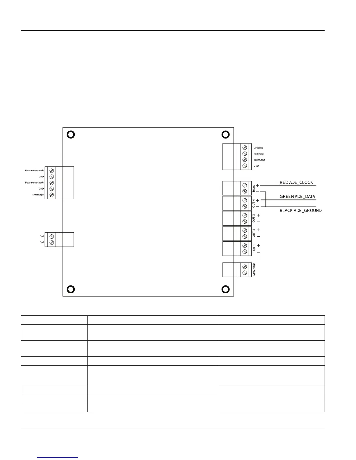
Circuit Board Diagram
Figure 21: Configuring Input/Output
Input/Output Description Terminal
Output 1 Passive max. 30V DC, 20 mA
Max. Frequency 100 Hz
OUT1 (+) and (–)
Output 2 Passive max. 30V DC, 20 mA
Max. Frequency 100 Hz
OUT2 (+) and (–)
Output 3 Passive Max 30V DC, 20 mA OUT3 (+) and (–)
Output 4 Passive Max 30V DC, 20 mA
Can be used with digital input as an ADE interface.
OUT4 (+) and (–)
RS232 Modbus RTU RxD, TxD, GND
IN Digital input 3…35V DC IN (+) and (–)
M-BUS M-Bus interface No polarity
M-Series® M5000 Electromagnetic Flow Meter
Page 16 September 2013
| sales@mvandc.com | Phone: 877.566.3837 | Fax: 925.407.2903