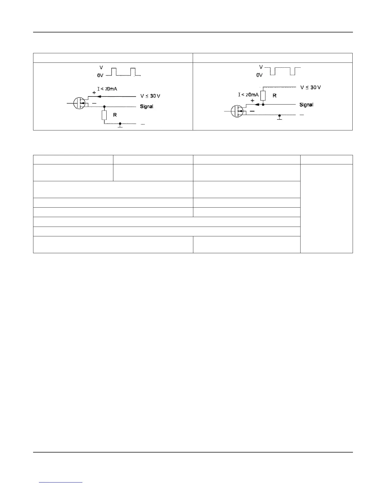
Digital Output Wiring Diagrams
Positive Pulse Logic Negative Pulse Logic
Figure 22: Digital Output Wiring Diagram
Digital Output Selections
Output 1 Output 2 Output 3 Output 4
Forward Pulse Output Reverse Pulse Output
Flow direction
(Forward vs. Reverse)
ADE
Flow Setpoint
(0…100% of full scale, resolution 1%)
Flow Setpoint
(0…100% of full scale, resolution 1%)
Empty pipe alarm Empty pipe alarm
Error alarm Error alarm
Off
Test
Can be used with AMR when the pulse width is set to
50 milliseconds.
—
Outputs are configurable for Pulses/Unit (PPU) and Pulse Width (PW). The PW is configurable from 5…500 milliseconds, with a
frequency limit is 100 Hz. The PPU is displayed using an automatically selected resolution.
The high/low flow alarm functionality is configurable for maximum and minimum setpoints as a percentage of full-scale flow.
Configurable values are settable from 0…100% in 1% increments.
User Manual
Page 17 September 2013
| sales@mvandc.com | Phone: 877.566.3837 | Fax: 925.407.2903