Remote Mount Installation
If you are installing the M5000 amplifier in a remote location, review the procedures in this section.
Mount Bracket to Amplifier
1. Align bracket-mounting holes with amplier mounting holes.
2. Attach bracket to amplier with supplied screws. Torque the screws to 80 inch-pounds.
Wiring Configuration
Wiring between the detector and the M5000 amplifier comes complete from the factory. If your installation requires the use
of conduit, we recommend that you follow these steps when wiring the detector to the amplifier.
1. Carefully remove the wires connected to the terminal blocks that run to the M5000 amplier or to the junction box.
See the chart below for a reference of wire color to terminal connection.
2. Run cable through the conduit while retaining the wiring of the cable to the amplier or the junction box, as supplied.
3. Complete conduit assembly on both ends and rewire the cable as it was previously wired.
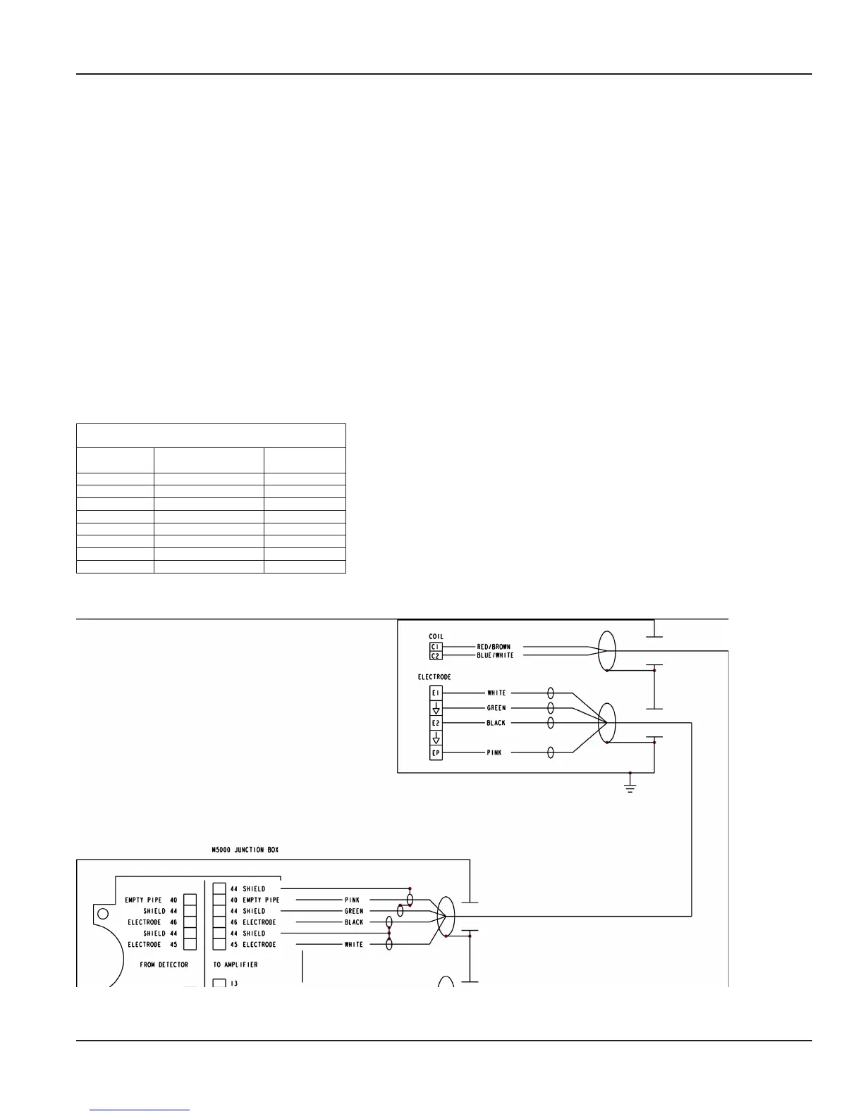
Wiring for Remote Configuration
Remote style M5000 amplifier models can be ordered with standard cables measuring 15, 30, 50 and 100 feet.
Junction Box
Connection
No.
Description Wire Color
11 Coil Red/Brown
12 Coil Blue/White
13 Main Shield Not Used
40 Empty Pipe Pink
44* Shield Green
44* Empty Pipe Shield Shield Wire
45 Electrode White
46 Electrode Black
*Connections with the No. 44 are lying on the same potential.
M5000 AMPLIFIER
Figure 20: Wiring for Remote Configuration
User Manual
Page 15 September 2013
| sales@mvandc.com | Phone: 877.566.3837 | Fax: 925.407.2903