7.EtherNet/IP Connection Procedure
9
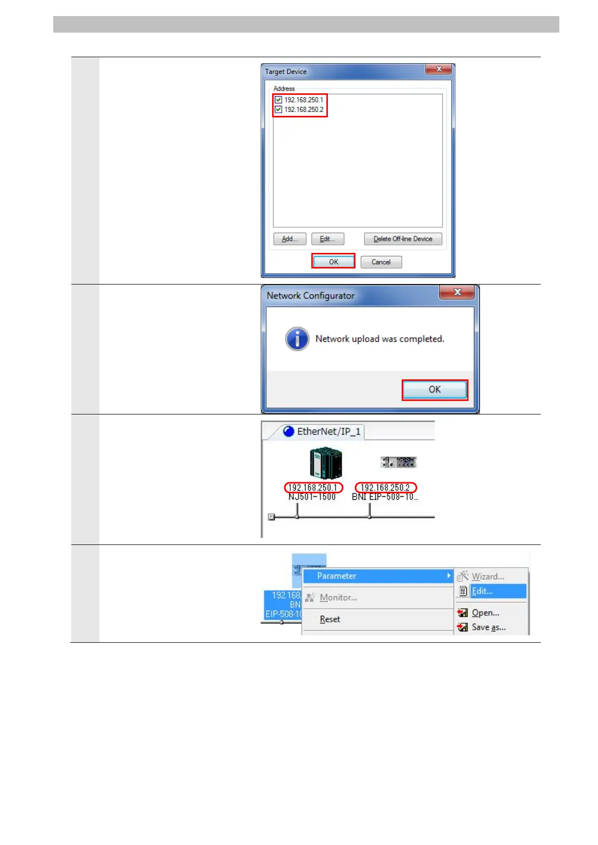
The Target Device Dialog Box
is displayed.
Select 192.168.250.1 and
192.168.250.2.
Click OK.
*If 192.168.250.1 and
192.168.250.2 are not
displayed in the dialog box,
click Add to add the
addresses.
*The displayed address varies
with the status of Network
Configurator.
The parameters of Destination
Device are uploaded.
After completing the upload,
the dialog box on the right is
displayed. Check the contents
and click OK.
Check that the nodes with the
following IP addresses are
configured in the Network
Configuration Pane.
・Controller (Node 1)
IP address: 192.168.250.1
・Network Module (Node 2)
IP address: 192.168.250.2
12
Right-click the device icon of
Network Module (Node 2) and
select Parameter - Edit from
the menu.
 Loading...


