Balluff Network Interface CC-Link IE Field Basic
www.balluff.com
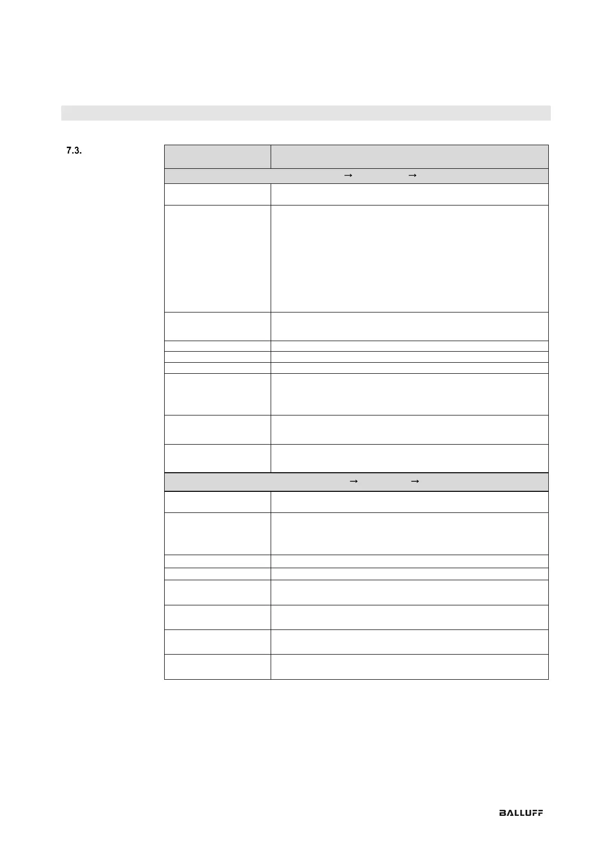
Direction: Slave Master (CIB PLC)
Input X 0-F (port 0-7,
pin 2/4)
Digital input signal for the corresponding pin (high active, active if 1,
inactive if 0)
Diagnostics
In-/output 0 - F
Error on corresponding input/output pin (if 1):
• Short circuit between pin and GND when pin configured as
output and set to active (PNP module).
• Short circuit between pin and UA when pin configured as output
and set to inactive (PNP module).
• Short circuit between pin and UA when pin configured as output
and set to active (NPN module).
• Short circuit between pin and GND when pin configured as
output and set to inactive (NPN module)
Error on the corresponding supply line of the port (if 1)
e.g. overcurrent, short-circuit on Pin 1.
1, if voltage on US is less than 18V
1, if voltage on UA is less than 18V
1, if voltage on UA is less than 11V or no voltage on UA
1 if an IO-Link device is connected and IO-Link communication is
running.
If IO-Link Validation is active, the result of the validation is indicated
by this bit.
IO-Link Channel 0-7
Event Flag
1 if an event from a connected IO-Link device is pending.
IO-Link Channel 0-7 Data
Valid Flag
1 if an IO-Link device is connected, IO-Link communication is
running and the process data from the IO-Link device is valid.
Direction: Master Slave (PLC CIB)
Output X 0-F (port 0-7,
pin 2/4)
Digital output signal 00h – 0Fh
Port direction
0 – F Pin2/4
When setting the port direction:
Bit = 0: the corresponding pin functions as a digital input
Bit = 1: the corresponding pin functions as a digital output
Used only during initial processing or reconfiguration
When setting the bit to 1 the red LEDs on the display come on
When setting the bit to 1 the green LEDs on the display come on
If set to 1, no changes can be made on the display. A key symbol is
displayed.
Activate IO-Link
Channel 0-7
If set to 1, the channel runs in IO-Link mode. Used only during initial
processing or reconfiguration
IO-Link Channel 0-7
Event Clear
If set to 1, then all Events of the IO-Link channel are cleared. If the
bit remains at 1, all new Events are automatically cleared.
IO-Link Channel 0-7
Byte Swap
If set to 1, Byte Swap is enabled. Used only during initial processing
or reconfiguration