The module is secured by means of two M6 screws and two washers.
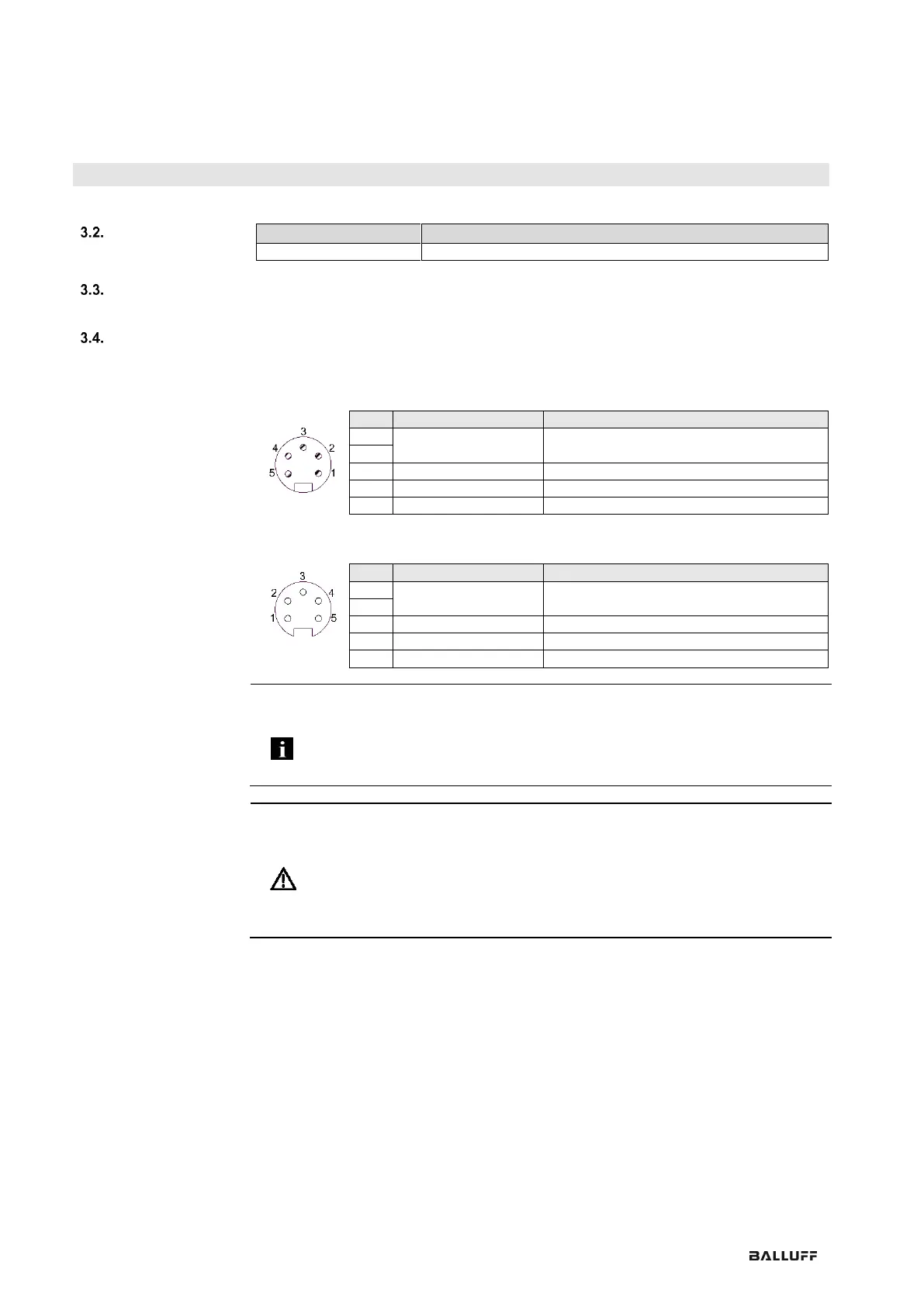
Supply voltage (7/8", 5 pins, male)
GND for module/sensor and actuator supply
Module/sensor supply (US)
Voltage output (7/8", 5 pins, female)
GND for module/sensor and actuator supply
Module/sensor supply (US)
Note
Where possible, use a separate power source to supply the sensor/bus and actuator
with power.
Total current < 9 A. The total current draw for all modules may not exceed 9A even
when connected in series.
Recommended fuse 8A.
Attention!
Do not separate supply voltages
Non-separate voltage supply circuits for sensor and actuator can result in
undesired voltage drops in the sensor supply when switching actuators.
► Therefore always use separately protected voltage supplies for sensors and
actuators.
Also be sure to sufficiently dimension the voltage supply of the device in order to
cover startup and peak currents. Design the fusing concept accordingly.