www.balluff.com 17english
5
Configuration and parameterization (continued)
5.4 Setting the number of magnets
BTL7-V50D-… can evaluate up to 16magnets depending
on the length. In normal mode, it is recommended to set a
fixed number of magnets, as this reduces susceptibility to
malfunctions, and increases the processing speed. In
flexible magnet mode (FMM), the number of magnets is
variable.
For magnets that are not detected or parameterized, the
error value 0x7FFFFFFF is output as position and speed.
If more magnets than parameterized are located in the
measuring range (with FMM, more than 16), the excess
magnets are ignored. BTL7-V50D-… always evaluates the
magnets from the plug side regardless of other settings.
The number of magnets can be set in the Config Assembly
in the Number_of_Magnets entry if Config_Assembly_
Parameter_Recognition is set to 1. Otherwise the value set
in object100, Attribute6: Number of magnets (Number of
Magnets), is valid. The sensor is set to one magnet as
factory default. If the number of magnets is set to 0, the
sensor is in the Flexible Magnet Mode (see also
chapter5.2 Attributes of the device configuration
object on page13 and chapter 5.3 Parameterization
using the Config-Assembly on page16).
Flexible Magnet Mode (FMM)
In flexible magnet mode, the number of magnets is not
specified. The BTL7-V50D-... accepts any number of
magnets up to a maximum of 16 and even changes to the
number during operation. However, after changing the
number, this is signalized by the output of error value
0x7FFFFFFF on all magnets. This error value is taken back
after a configurable time in the parameter FMM Timeout.
The new number of magnets is accepted once this period
has elapsed. If no magnet is located in the detection
range, the error persists until at least one magnet is
detected. For magnets that are not present, the error value
0x7FFFFFFF is output as position and speed value.
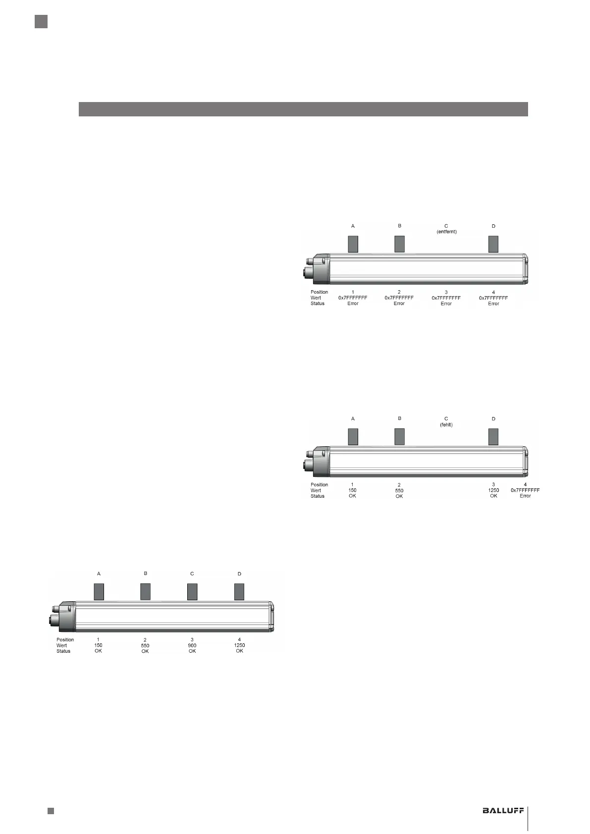
Fig. 5-2: Example with 4 magnets (exemplary style)
If, for example, you have four magnets (A, B, C, and D as
seen from the connector end), then magnet A is assigned
to position (or module) 1, magnet B to position 2, etc.
If magnetC is removed, an error value is output for all
positions for the time set in the Diagnostic time for FMM
parameter.
Fig. 5-3: Example: Magnet C removed (exemplary style)
After the set time has elapsed, the magnets are again
assigned in the order in which they are detected. In our
example only three magnets are still detected. These are
assigned to positions 1-3. The missing fourth magnet is
assigned to position 4, which remains on the error value.
Fig. 5-4: Example: Magnet reassignment (exemplary style)
Please note that the evaluation of the positions in the
controller must be adapted to this arrangement.
The parameter FMM Timeout is configured in the Config-
Assembly (if Config_Assembly_Parameter_Recognition is
set to 1, see chapter5.3.4 on page16) or in the device
configuration object (seeAttribute16: FMM timeout on
page15).
BTL7-V50D-…
Configuration Manual

 Loading...


