Bandit
84
Copyright 12/17
MODEL 20XP
HYDRAULIC PUMP CHECK OUT
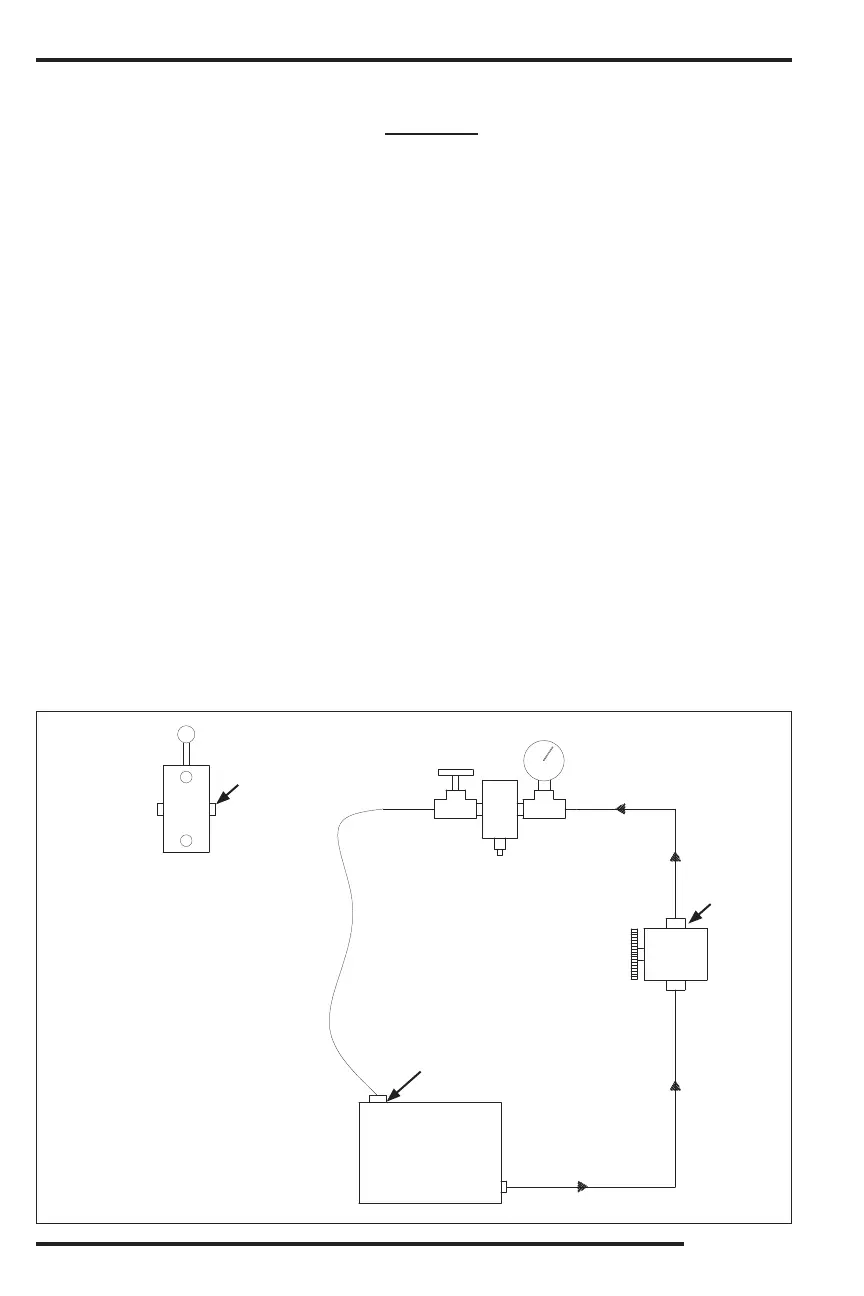
HYDRAULIC PUMP CHECK WITHOUT USING A FLOW METER
To check out the hydraulic pump the mechanic will need a needle type control valve, a pressure gauge capable
of reading 3000 psi (207 bar), an in-line 2500 psi (172 bar) relief, and a hose long enough to span between
the pump and the hydraulic tank.
1. Disconnect the pressure line going from the pump at the rst component and cap the tting at the component.
2. Attach a Tee tting to the end of the pressure hose (which was removed from the component) and install
the Tee tting and gauge.
Attach an in-line 2500 psi (172 bar) relief to the Tee tting with the gauge.
4. Attach the hydraulic ow control valve to the in-line relief and the hose (you supply) to the outlet port of
the ow control valve.
5. Make sure the pressure gauge is installed up stream from the ow control valve. Failure to do
this will cause serious damage to the hydraulic pump when testing.
6. If the hydraulic oil tank is equipped with a mesh strainer in the ll neck, remove it and place the open
end of the hose (you supply) into the tank ll neck.
7. MAKE SURE THAT THE FLOW CONTROL VALVE IS FULLY OPEN SO AS TO ALLOW
UNRESTRICTED FLOW TO PASS THROUGH IT.
Start the engine to engage the pump, the clutch may have to be engaged if the pump is belt driven.
9. Have a second person lift the hydraulic hose far enough out of the tank inlet to observe the ow of oil
going into the tank. Observe the pressure gauge reading to make sure a high pressure does not exist.
10. Increase the engine speed slowly to full rpm and at the same time observe the pressure. This should
still remain low.
SLOWLY
turn the needle valve on the ow control in and observe the pressure increase on the pressure
gauge.
12. Continue closing the ow control valve until the pressure gauge reading reaches 90% of the normal relief
valve setting (example: if system operates at 2500 psi (172 bar), do not exceed 2250 psi (155 bar).
Never allow the pressure to go more than 90% of the main relief pressure.
13. If the pump is good there should be no noticeable decrease in the ow rate coming out of the hose and
into the hydraulic tank.
14. If 90% of the main relief pressure can not be obtained and/or the ow rate of the hose is considerably
less, then the pump is worn or damaged.
Do not exceed
90% of system
pressure.
First
component
after pump.
Hose
supplied by
you.
Flow
Direction
Hydraulic
Tank
Pump
Outlet
Flow
Direction
Tee
Fitting
Gauge
Flow Control
Valve
Cap after
removing
hose.
Remove any ller
neck screen.
In-Line
Relief
0
0
0
0
0
0
0
0
0
0
0
0
HYDRAULICS