Bandit
86
Copyright 12/17
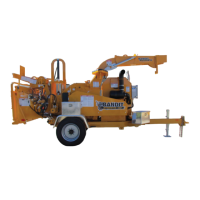
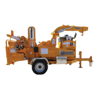
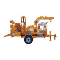
MODEL 20XP
HYDRAULIC MOTOR CHECK OUT
HYDRAULIC MOTOR CHECK OUT FOR MACHINES WITH LIVE HYDRAULICS
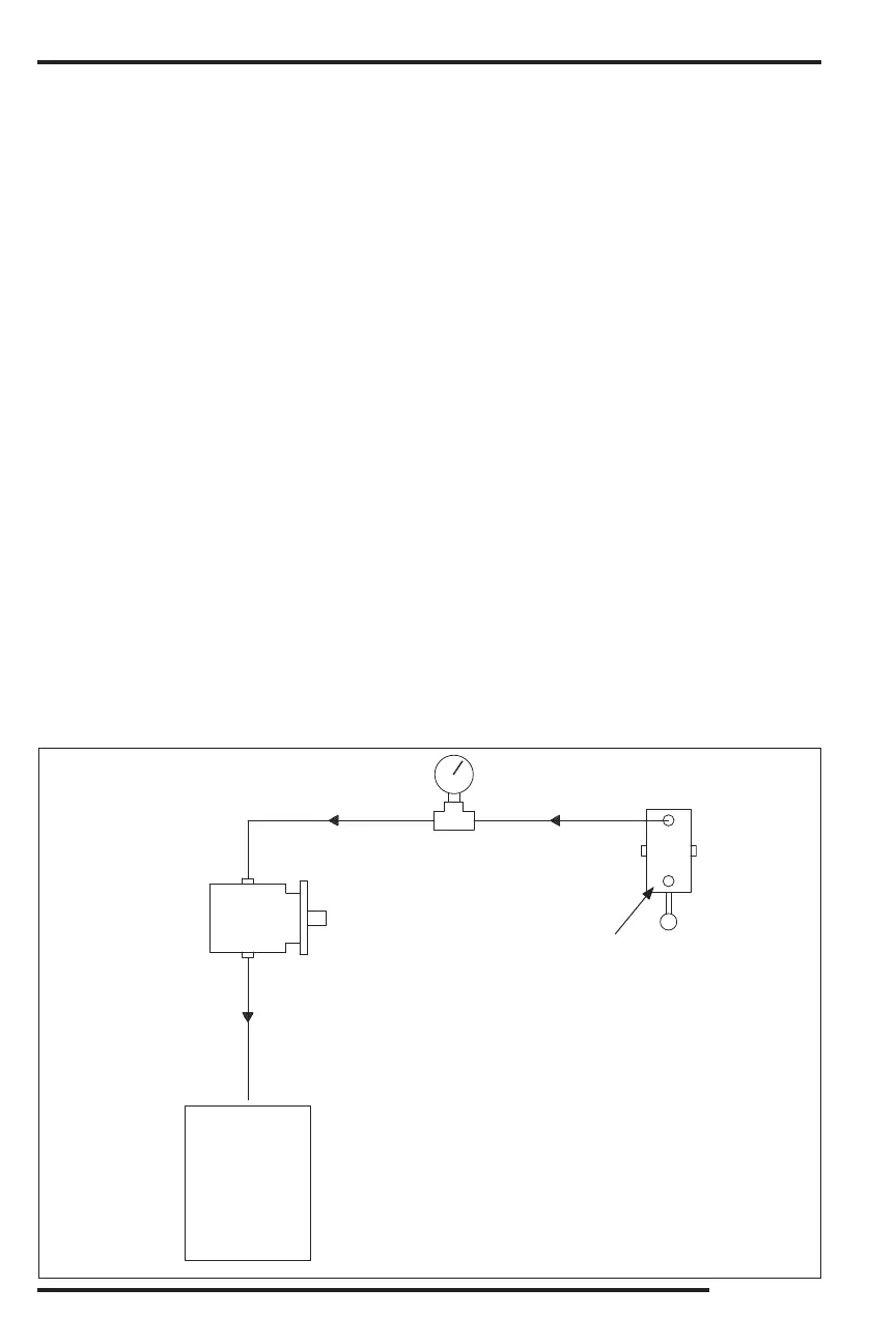
To check out the hydraulic motor the mechanic will need a pressure gauge capable of reading 3000 psi (207
bar), a Tee tting to install to the control valve, a plug tting to install in the control or relief valve, and a clean
5 gallon (19L) pail.
1. The following instructions are for machines with Live Hydraulics, for machines without Live Hydraulics
contact your local dealer or Bandit Industries.
2. In order to check out a hydraulic motor, it is necessary to mechanically stop the motor from turning
while under load. The hydraulic pump needs to be driven without turning the chipper disc/drum (Live
Hydraulics). Feed a reasonably large size log into the machine until it contacts the stationary disc/drum.
This should stall the hydraulic motor(s). It may also be necessary to apply down pressure by operating
the yoke control valve (if equipped).
3. With the feedwheel(s) mechanically locked as described, turn the engine o and keep the key in your
possession. If the hydraulic motor does not have a case drain, unhook the hose going from the hydraulic
motor back to the control valve at the valve, some machines will be equipped with a ow divider between
the hydraulic motor and the control valve. If the hydraulic motor has a case drain, unhook the case drain
hose that goes to the relief valve at the valve and put the hose into the hydraulic tank.
Place the end of the hose in a clean 5 gallon (19L) pail.
Plug the open port of the control valve or main relief valve.
6. Unhook the other hose in the control valve and install a Tee tting into the control valve and attach the
hose to the Tee tting.
Install a pressure gauge in the other port in the Tee tting to monitor hydraulic pressure.
Put the infeed control valve in the center position and start the engine.
Increase the engine speed slowly to full rpm.
10. Operate the infeed control valve to feed the log into the stationary disc/drum. If the feedwheel(s) try to
turn, apply down pressure by using the yoke control valve (if equipped).
11. Providing the pump and the relief are functioning properly, the pressure gauge should read the speci ed
main relief setting.
Observe the amount of hydraulic uid coming from the hose into the pail. If the amount of leakage in
the pail is 1 g.p.m. (3.8 L.p.m.) or less the motor is good. If the amount of leakage in the pail is over
1 g.p.m. (3.8 L.p.m.) the motor needs to be replaced.
Hydraulic
Motor
Flow
Direction
Tee
Fitting
Flow
Direction
Control
Valve
Gauge
Clean
5 Gallon
Pail
Plugged
Port
0
0
0
0
0
0
0
0
0
0
0
0
HYDRAULICS