Technical data • Entire device
Chapter 2
Technical data
71Panel PC 700 with 945GME N270 CPU board User's Manual V 1.16
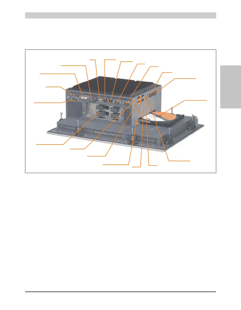
2.4 Device interfaces
The following image shows the general and optional device interfaces for an entire
Panel PC 700 unit.
Depending on system unit, the device interfaces will vary only in the number of PCI slots and the
presence of a slide-in drive slot.
Status LEDs
COM1
COM2
Hardware security
key (dongle)
Ethernet2
(ETH2)
USB
Voltage supply
MIC, Line IN
Line OUT
Add-on
interface slot
Ethernet1
(ETH1)
Battery
PS/2 keyboard or
PS/2 mouse
Reset
button
Power
button
CompactFlash
slot (Cf1)
Add-on drive slot
(HDD / Cf2)
PCI slot(s) - 0, 1 or 2
Slide-in 1
drive insert slot
Monitor/Panel
SDL (Smart Display Link) / DVI
1)
1)
1)
Depends on system unit
 Loading...