Registers 1001 [31:16], 1002 [15:0] store the first floating point value; registers 1003, 1004 store the second floating
point number. There are a total of 250 floating point values; they are addressed as two 16-bit pieces to accommodate the
Modbus protocol.
Use these registers when reading/writing external devices that require Modbus registers in floating point format. Since
Modbus transactions are 16-bits, the protocol requires two registers to form a 32-bit floating point number.
7.3 Virtual Registers
The
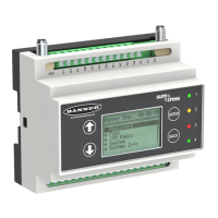
DXM Controller has a small pool of virtual registers that show internal variables of the main processor. Some register
values will be dependent upon the configuration settings of the DXM Controller.
Registers Definition
10001 GPS latitude direction (N, S, E, W) GPS Coordinate Data if the DXM is configured to read an external GPS unit.
10002 GPS latitude
10003 GPS longitude direction (N, S, E, W)
10004 GPS longitude
10011–10012 Resync timer Engineering use
10013–10014 Resync timer rollover Engineering use
10015–10016 Reboot cause (Restart Codes above) Reboot Type
10017–10018 Watchdog reset count Counter to track how many resets have been caused by the Watchdog
10021 IO Board Battery Voltage (mV) DXM Base I/O board battery / solar charger statistics.
Refer to the DXM Instruction Manual for more information.
10022 IO Board Battery Charging Current (mA)
10023 IO Board Incoming Supply (mV)
10024 IO Board On board thermistor ( degrees C)
10025–10026 Http Push SSL Acquires Statistical counts of connections, disconnections and forced disconnects when
the DXM Controller creates a connection using SSL/TLS (Encrypted
connections)
10027–10028 Http Push SSL Releases
10029–10030 Http Push SSL Forced Releases
10031–10032 Http Push Attempts Statistical counts of connections, disconnections and forced disconnects when
the DXM controller creates a connection using HTTP non-encrypted
10033–10034 Http Push Successes
10035–10036 Http Push Failures
10037–10038 Http Push Last Status Last DXM Controller push status
10039–10040 Cellular Strength, BER Cellular signal strength. Value range: 0–31
0 = –113 dBm or less
1 = –111 dBm
2–30 = –109 dBm through –53 dBm in 2 dBm steps
31 = –51 dBm or greater
99 = not known or not detectable; BER not used
10100 Number of read maps in default Read Map statistics
10101 Number of read map successes
10102 Number of read map timeouts
10103 Number of read map errors
10104 Read map success streak
10105 Number of write map successes Write Map statistics
10106 Number of write map timeouts
10107 Number of write map errors
10108 Write map success streak
DXM100 Controller Instruction Manual
www.bannerengineering.com - Tel: 763.544.3164 45

 Loading...