9
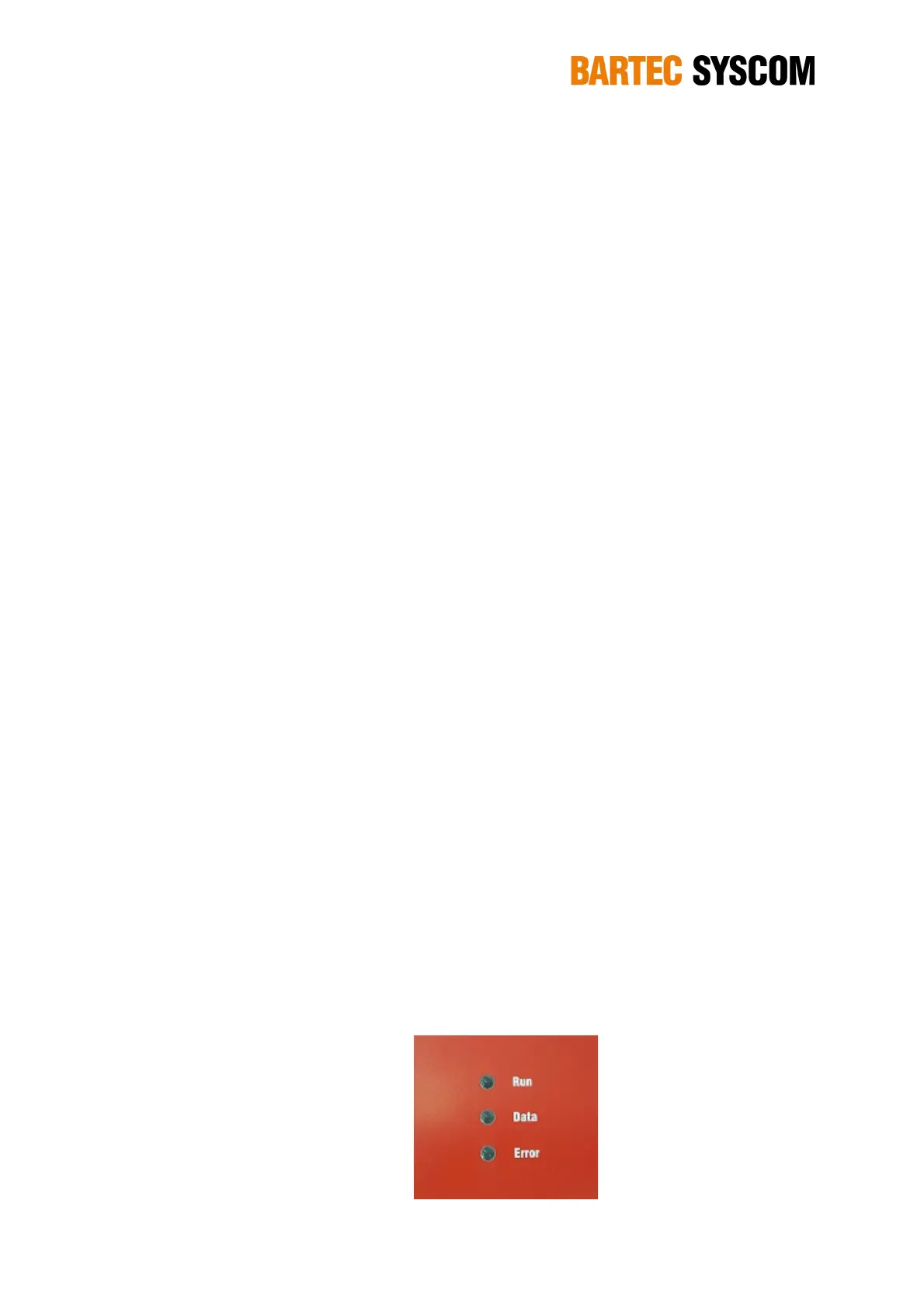
2.2.1. Power
Here you connect the MR3000DMS to:
• the main power (100-240VAC, 50-60 Hz) in case the AC version has been purchased
• to an external DC (10-36 VDC) source if the DC version has been purchased
2.2.2. LAN
Here you connect the Fiber optic cable – for further detail check chapter 3.1.1 and 3.1.2.
M20 cable gland 6-13 mm and ST connectors are used. The FO type that should be used is
Multimode OM2 fiber with wavelength 1300 nm, 50/125 μm, Rx/Tx, ST connectors.
If the kit LAN has been ordered, the DMS interfaces to a standard 10/100-BASE LAN.
2.2.3. GPS (optional)
In case the GPS kit has been ordered, here you connect to an appropriate GPS module for time
synchronization.
2.2.4. Relays
Here you connect a relay cable to the terminals. 3 available relays with NO, NC, COM wires (9
wires) and 1 ground. The cable gland referred to the relays are M16 cable gland 7-11 mm.
For further detail on the electric scheme check Section 2.4.9, while for the software settings please
look at Section 5.4.7.
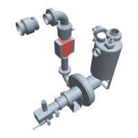
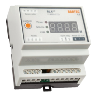
2.3 Status LEDs
There are three status LEDs.
The green RUN LED is on if the MR3000DMS is active and blinking while the unit is starting up.
The yellow DATA LED is on if the MR3000DMS is recording an event.
The red ERROR LED indicates if any error or warning occurs on the MR3000. If it blinks slowly,
then a warning has been detected, if it is permanently ON (red colour) then an error has been
detected.
Figure 2.3.1. Led panel on the MR3000DMS.