Functional Description
3-4
Output Relays
There are eleven form C output contacts available for external connection. They are all electrically isolated
from each other (that is, they do not share common connections). There is one set of contacts for each of
the nine relay protective functions and one each for the sync-check and watchdog timer (fail-safe)
annunciation. If auto reset is disabled, the output contacts are sealed in. If auto reset is enabled, the
output contacts remain closed only as long as the relay detects a fault.
RS-232 Channel
The serial link present in the microprocessor connects to an opto-isolated RS-232 level shifting circuit.
This permits direct connection to the interface on the side panel of the relay using a personal computer for
programming. Communications protocol is compatible with readily available modem software that
emulates a dumb terminal.
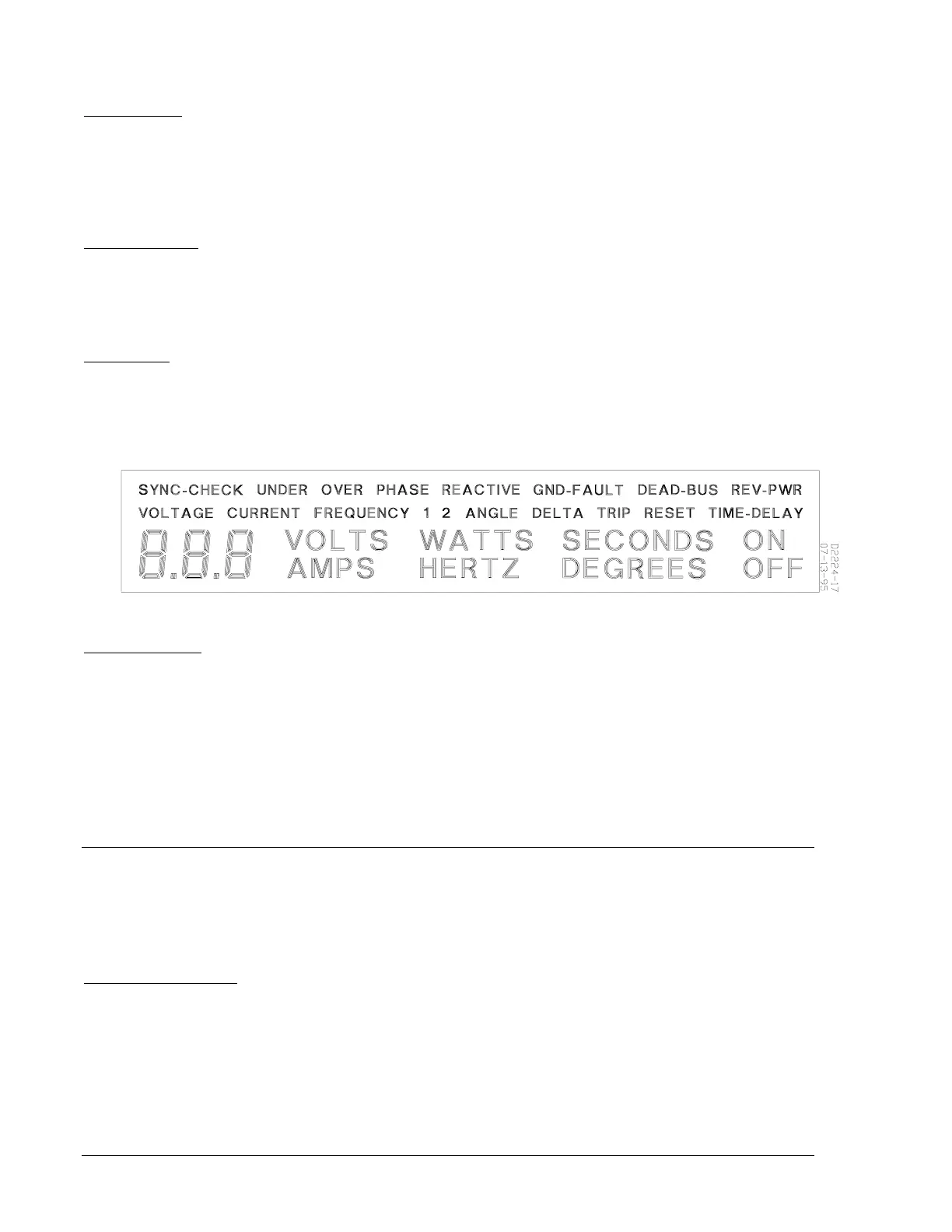
LCD Display
The front panel liquid crystal display (LCD) is a customized display with both descriptive word segments
and a three digit numerical display area. Software in the microprocessor controls which segments are on
at any given time. The user interface and the protective functions are the major uses for the display,
which is shown below in Figure 3-2.
Timing Functions
The relay has a time delay function for each of the different protective functions (overvoltage,
underfrequency, sync-check, etc.). All of the delays serve to allow for any abnormal occurrences to
correct themselves. For instance, if an over voltage occurs, the time delay may be between zero and
twenty seconds (as programmed). If the overvoltage condition returns to normal within the delay window,
the system ignores the previous overvoltage and instantly resets. The timing functions give a standard
delay range of 0 to 20 seconds, except for the following.
•
Sync-Check 0.0 to 2.0 seconds
•
Neutral Ground Fault 0.2 to 2.0 seconds
•
Overcurrent Timing Curves
SOFTWARE
Software embedded in the microprocessor controls all aspects of BE3-GPR functionality. This comprises
power-up initialization, user front panel setup and configuration, hardware jumper input detection,
protective function trip detection and annunciation, sync-check monitoring and annunciation, and remote
RS-232 communications support.
Power-Up Initialization
When battery power is first applied, the relay initiates a power-up sequence. This loads all unit
configuration data stored in nonvolatile EEPROM into the main memory of the relay. Then, all segments
on the front panel LCD and the sync-check LED illuminate for one second to allow the user to visually
check the display operation. Following this sequence, the LCD displays ON (Shown as the first display in
Figure 3-3, Sheet 1 and referred to as the ON screen). If the last power down occurred during a tripped
condition, the display will show this last trip for ten seconds. Following this sequence, the LCD displays
ON and the software immediately activates the enabled functions and monitors the generator and bus
inputs.
Figure 3-2. LCD Display