13-6 9492600990
Power System Stabilizer DECS-150
The logic limiter compares the signal from the washout filter with the Logic Limiter Upper and Lower Limit
Settings. If the counter reaches the set delay time, the time constant for the washout filter changes from
the normal time constant to the limit time constant. When the signal returns to within the specified limits,
the counter resets and the washout filter time constant changes back to the normal time constant.
Figure 13-8 illustrates the washout filter and logic limiter.
Figure 13-8. Washout Filter and Logic Limiter
Output Stage
Prior to connecting the stabilizer output signal to the voltage regulator input, adjustable gain and upper
and lower limits are applied. The stabilizer output is connected to the voltage regulator input when the
software switch SSW 10 setting is On. Processing of the stabilizer output signal is illustrated in Figure
13-9.
Figure 13-9. Output Stage
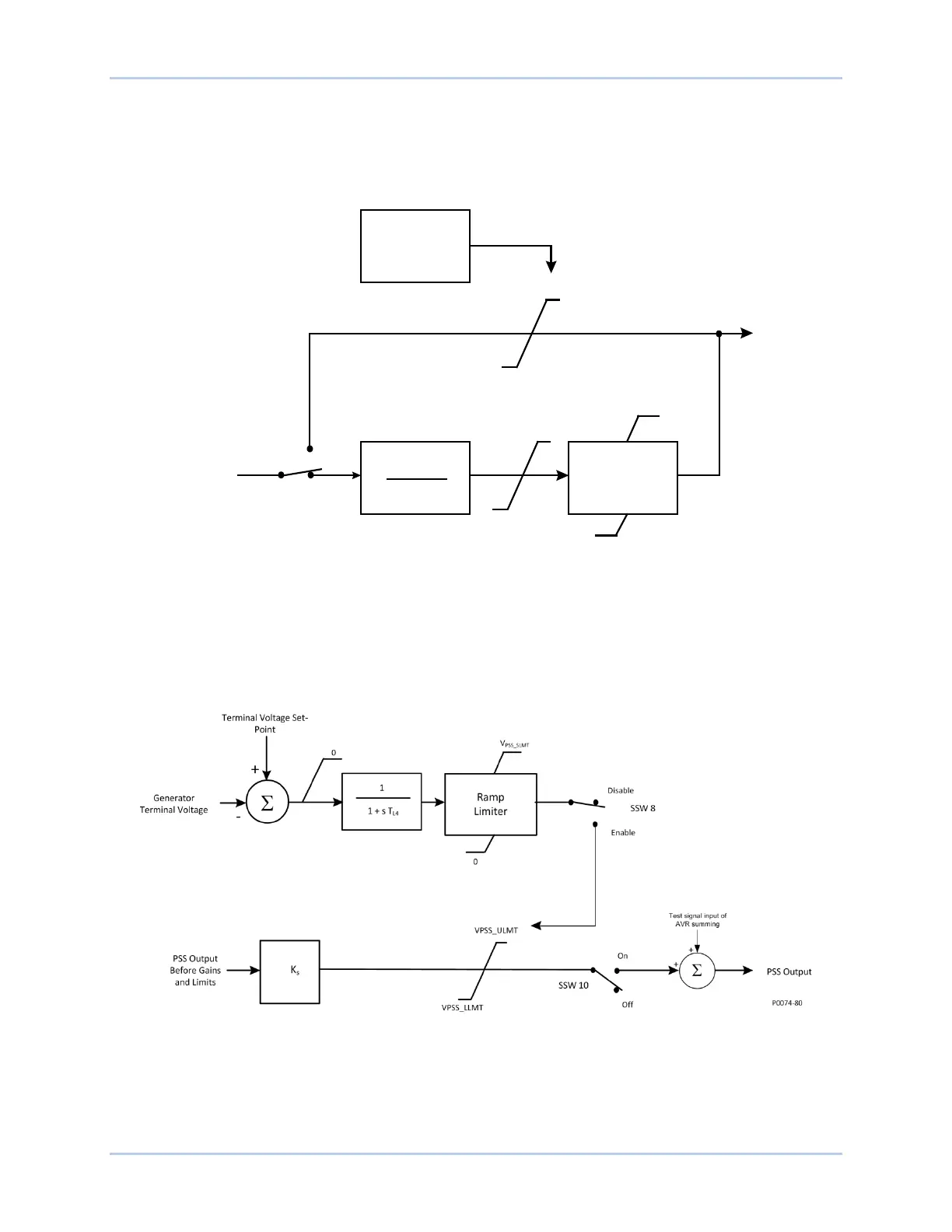
Terminal Voltage Limiter
Since the PSS operates by modulating the excitation, it may counteract the voltage regulator’s attempts
to maintain terminal voltage within a tolerance band. To avoid creating an overvoltage condition, the PSS
has a terminal voltage limiter (shown in Figure 13-8) that reduces the upper output limit to zero when the
SSW 9
Logic Limiter
V
lmt_lo
V
lmt_hi
s T
w5
1 + s T
w5
V
PSS_ULMT
V
PSS_LLMT
V
PSS_ULMT
V
PSS_LLMT
Phase Lead
Block
V
ST
Terminal
Voltage Limiter
P0026-22
12-13-04
Disable
Enable