WARNING
WARNING
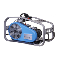
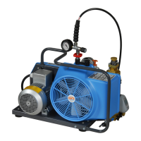
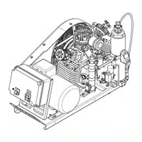
Instruction Manual Breathing Air Compressors
28
4.5.1. INTAKE FILTER
DESCRIPTION
A dry micronic filter is used to filter intake air, see Abb. 41.
Abb. 41 Intake filter
1
MAINTENANCE
The filter cartridge must be cleanded or changed at regular
intervals according to maintenance schedule in chapter 4.3.
Do not use any cleaning fluids which
are a hazard to respiration.
To clean, remove micronic filter cartridge (1) and clean with
brush or by blowing air inside out. Clean filter housing inside
with a damp cloth. Take care to prevent dust from entering
intake pipe.
INTAKE HOSE WITH PRE-FILTER
Petrol or diesel driven breathing air compressors should be
fitted with an intake hose and a pre-filter which is also recom
mended for electric power driven compressor units. It en
sures clean air, free of exhaust fumes, being compressed.
For positioning of the pre-filter refer to chapter 3.
MAINTENANCE
Change the pre-filter in the same intervals as the intake filter.
At replacement make sure that only a hose
with same length and inner diameter is
used.
4.5.2. INTERMEDIATE SEPARATOR
DESCRIPTION
An intermediate separator is mounted on the compressor
after the 2nd and 3rd stage. The separators are designed to
remove water and oil accumulating due to cooling the air
down after the compression process.
Separation is achieved by means of centrifugal action pro
vided by a vortex plate.
LIFETIME
The separators are subject to dy
namic load. They are designed for a
certain number of load cycles, which
originate from an abrupt pressure loss at condensate
drain (1 load cycle i.e. condensate drain = 1 depressu
rization, 1 pressurization). After reaching the max.
number of load cycles the separators must be replaced,
otherwise the housing may burst due to material fa
tigue. Refer to the pressure vessel operating manual de
livered with the unit.
The maximum recommended amount of four load cycles per
hour should not be exceeded. If it is possible to regulate the
operation of the unit to such a degree as to achieve four load
cycles per hour, in our opinion this would be an optimum be
tween usage and actual life.
To avoid exceeding the max. number of load cycles the oper
ating hours should be recorded in the service manual.
MAINTENANCE
Proper operation of the individual compression stages will
rely on the intermediate separator being properly serviced.
Drain condensate every 15 to 30 minutes
from the separator or ensure that the auto
matic condensate drain unit drains reg
ularly (see chapter 4.5.10.).
4.5.3. FILTER SYSTEM P31
APPLICATION AND SUMMARY DESCRIPTION
The air leaving the final stage is cooled in the after-cooler to
approx. 10 - 15 °C (18 - 27 °F) above ambient temperature
and then enters filter system P31 with TRIPLEX longlife car
tridge (Abb. 43).
The filter assembly consists of separator and cartridge
chamber. In the separator underneath the cartridge
chamber, liquid oil and water particles are reliably separated
from the compressed medium by a pipe nozzle. Residual oil
and water vapors are then removed by the TRIPLEX longlife
cartridge. The quality of the breathing air produced con
forms to DIN EN 12021.