Instruction Manual Breathing Air Compressors
44
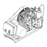
Abb. 59 Condensate separator
3
4
5
6
7
10
9
8
2
1
4.5.11. ELECTRICAL SYSTEM
This section describes the standard electric control system of
the compressor unit. The amount of built-in components
varies depending on order.
For schematic diagrams, see annex.
ELECTRIC UNITS
The electrical equipment of the compressor unit consists of:
• drive motor M1
• motor protection switch (standard)
• electric control system (optional), containing:
- switch box containing air break contactor K1 or
star-delta contactor K1-K3 with time relay K4
- service switch S3
- final pressure switch F16
- timer for automatic condensate drain K10
To start the electric motor and enable the functioning of the
controls as well as the monitors, the following components
are essential:
• main switch Q1 and main fuse, both to be installed by the
customer.
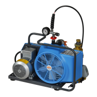
Drive engine
The compressor unit is driven by an electric motor by means
of V-belts. Check the V-belts regularly for tension and wear.
See chapter 4.5.12. Except for external cleaning, the drive
motor requires no servicing. The motor bearings may need
lubricating, depending on the model. Please observe the in
structions written on the motor.
Motor protection switch
Protection of the motor is ensured by the thermomagnetic
releases integrated into the motor protection switch.
Abb. 60 Motor protection switch
12
The response value of the electromagnetic releases (protec
tion against short-circuit) is preset. The motor is switched on
manually by pressing the start button (1). It is switched off
either manually by pressing the stop button (2) or automati
cally by a thermic release. For safety of the operating person
nel all voltage carrying parts have a protective cover. On units
with low volt releaser the motor protection switch is also re
leased during power failure. Thereby operating personnel are
protected from unintentional start-up in power return.
The motor can only be restarted by pres
sing the start-button.
Semi-automatic compressor control (optional)
Unit switches off automatically when the final pressure is re
ached in the pressure system connected to the compressor.
Restart the unit manually by pressing operation button 1 on
the control and monitoring unit.
Pressure switch (optional)
Switching on and/or off of the compressor unit is controlled
by pressure switch F16. The upper threshold value is adjust
able as follows.