Instruction Manual Breathing Air Compressors
7
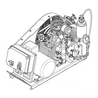
Air flow diagram
See Abb. 10. The air is drawn in through intake filter -5, com
pressed to final pressure in cylinders -1, -2, -3, and -4, and re
cooled by inter-coolers -6, -7 and -8, and after-cooler -9. The
safety valves -13, -14, -15 and -16 protect the pressure of the
single stages.
The compressed air is purified by interfilters -10 and -11 and
filter assembly -12 which is fitted with a Triplex cartridge -17.
The interfilters -10 and -11 and filter assembly -12 are drained
by condensate drain valves -18. Pressure maintaining valve
-19 keeps the pressure constant within filter assembly -12.
Through filling hose -20 and filling valves -21 the compressed
and purified air is conducted to the bottles to be filled. Filling
pressure can be read from pressure gauge -22.
300 bar compressor units are available with a change-over
device -23 to fill 200 bar bottles. In this case, safety valve -24
(225 bar) takes over the function of the final safety valve -16
(330 bar).
5
6
7
8
9
10
11
12
13
1415
16
18
19
17
20
21
21
22
22
23
24
18
18
Abb. 10 Air flow diagram with filter system P31
1 Cylinder 1st stage
2 Cylinder 2nd stage
3 Cylinder 3rd stage
4 Cylinder 4th stage
5 Intake filter
6 Cooler 1st stage
7 Cooler 2nd stage
8 Cooler 3rd stage
9 After-cooler
10 Intermediate separator 2nd stage
11 Intermediate separator 3rd stage
12 Filter system P31 (Central filter assembly)
13 Safety valve 1st stage
14 Safety valve 2nd stage
15 Safety valve 3rd stage
16 Final pressure safety valve
17 Triplex filter cartridge
18 Manual condensate drain taps
19 Pressure maintaining valve
20 Filling hose
21 Filling connector
22 Filling pressure gauge
23 Change-over device 300 bar - 200 bar
24 Safety valve 225 bar