Instruction Manual Breathing Air Compressors
6
Compressor block IK12.14
The compressor block IK12.14 is used to compress air in the
high pressure range up to 420 bar (5,000 psi).
The compressor block is of a four stage, three cylinder design.
The cylinders are arranged in a W form, the 1st/2nd stage
vertical stepped cylinder in the centre, 3rd stage on the right,
and 4th stage on the left side looking from the filter side.
The compressor blocks are particularly suitable for continu
ous operation because of their rugged design and the corro
sion resistant intermediate filter and cooler assemblies.
Smooth running is a particular feature of this BAUER design.
The balance of masses of the 1st rank is zero. The moving
parts of the driving gear are all equally balanced. This results
in a vibration-free running. The driving gear is fitted with en
ergy saving cylinder roller bearings. The upper and lower
connecting rod bearings are also roller bearings. This allows
for an even longer life which lasts at least 30,000 operating
hours.
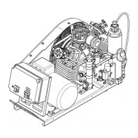
The design of the compressor block is shown in Abb. 9. For
the mode of operation refer to the flow diagram, Abb. 10.
2
1
13
9
16
5
4
6
8
7
10
11
12
14
17
19
3
15
18
Abb. 9 Compressor block, front view
1 Valve head, 1st stage
2 Safety valve, 1st stage
3 Intake manifold, 2nd stage
4 Oil filler neck
5 Cylinder, 4th stage
6 Safety valve, 3rd stage
7 Intermediate separator, 3rd stage
8 Inter-cooler, 3rd stage
9 Condensate drain tap
a)
10 Condensate drain connector
a)
11 Intake filter
12 Outlet manifold, 2nd stage
13 Cylinder, 3rd stage
14 Safety valve, 2nd stage
15 Oil filter housing
16 Intermediate separator, 2nd stage
17 Inter-cooler, 2nd stage
18 Oil drain plug
19 After-cooler, 4th stage
a) optional