EasyManua.ls Logo

Baumer NE214 User Manual

Baumer NE214
52 pages
Go to English
To Next Page IconTo Next Page
Page #1 background imageLoading...
Page #1 background image
10.12
171.51.161/4
81005184
Irrtum sowie Änderungen in
Technik und Design vorbehalten.
Subject to modifcation in technic & design.
Inhalt
1 Allgemeines / Sicherheitshinweise
2 Systembeschreibung
2.1 Beschreibung
2.2 Blockdiagramm
3 Gerät anschliessen
3.1 Betriebsspannung anschliessen
3.2 Elektronische Ausgänge belegen
3.3 Signalausgänge belegen
3.4 Signaleingänge belegen
3.5 Sensorversorgung anschliessen
3.6 Schnittstellen anschliessen
3.7 Testroutine durchführen
4 Bedienerebene
5 Programmierebene
5.1 Betriebsarten
5.2 Programmierzeilen
5.3 Zählweisen (Input modes)
5.4 Ausgangsverhalten (Output modes)
6 Technische Daten
6.1 Abmessungen
6.2 Werkseinstellungen
6.3 Fehlermeldungen
7 Bestellbezeichnung
Baumer IVO GmbH & Co. KG
Dauchinger Strasse 58-62
DE-78056 Villingen-Schwenningen
Phone +49 7720 942-0
Fax +49 7720 942-900
www.baumer.com
info.de@baumerivo.com
Betriebsanleitung
Elektronischer Vorwahlzähler
NE214
Contents Seite / Page
General / Safety instructions 2 / 28
System description 4 / 30
Description 4 / 30
Block diagram 5 / 31
Connecting 5 / 31
Connecting the voltage supply 6 / 32
Assignment electronic output 7 / 33
Assignment signal output 7 / 33
Assignment signal input 8 / 34
Connecting the sensor supply 8 / 34
Connecting interfaces 9 / 35
Executing the test routine 9 / 35
Operating mode 11 / 37
Programming mode 12 / 38
Operating modes 18 / 44
Programming lines 19 / 45
Counting modes (input modes) 20 / 46
Output responses (output modes) 20 / 46
Technical data 23 / 49
Dimensions 25 / 51
Default settings 25 / 51
Error messages 25 / 51
Part number 26 / 52
Operating Instructions
Electronic preset counter
NE214
Question and Answer IconNeed help?

Do you have a question about the Baumer NE214 and is the answer not in the manual?

Baumer NE214 Specifications

General IconGeneral
BrandBaumer
ModelNE214
CategoryCash Counter
LanguageEnglish

Summary

General Information and Symbols

Symbol Explanations

Explains symbols used in the manual for clarity and understanding.

Safety Instructions

General Safety Precautions

Details on product development, safe operation, and adherence to manual.

Proper Use Guidelines

Specifies correct application and operating conditions for industrial processes.

Installation and Maintenance Safety

Procedures for safe installation, commissioning, and maintenance.

System Description

Device Overview and Functions

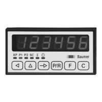
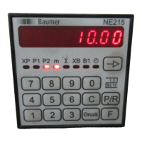
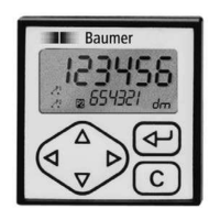
Overview of the 6-digit preset counter, its functions, and capabilities.

LED Indicators and Operating Controls

Explanation of LED indicators and the function of each operating field key.

Block Diagram and Connections

Electrical Connections Diagram

Illustrates the internal connections and signal flow of the counter.

Connecting the Device

Terminal Assignments

Details the function of each terminal and the 15-pole screw-type terminals.

Voltage and Sensor Supply Connection

Instructions for connecting AC/DC voltage and sensor supply.

Input and Output Signal Connections

Details for connecting electronic and signal (relay) outputs and inputs.

Connection Interfaces (Optional)

Information on serial port functions and interfaces like RS232, RS422, RS485.

Executing the Test Routine

Procedure for starting and extending the device's test routine.

Operating Mode Functions

Counter Status and Preset Adjustments

Reading and changing counter status, preset values P1, P2, and SC.

Totalizer and Hour Counter Operations

Reading and resetting the totalizer and hour counter values.

Programming Mode Structure

Programming Field Overviews

Details of programming fields 1, 2, and 3 for parameter configuration.

Key Assignment in Programming

Details functions of keys in both operating and programming modes.

Accessing and Navigating Programming

Code Entry and Validation

Steps to enter the code to access programming segments and handle errors.

Programming Segment 1 Parameter Changes

How to input new values for operating parameters in Segment 1.

Programming Segment 2: Status Control

Parameter Access Status Numbers

Defines status numbers 0, 1, 2 for parameter access control.

Modifying Parameter Status

Inputting status numbers to control parameter access on the operator level.

Programming Segment 3: Configuration

Operating Mode and Scaling Factor

Setting the operating mode and scaling range for the main counter.

Counting Mode and Frequency Settings

Selecting counting modes and configuring track A/B frequencies.

Programming: Input/Output and Key Logic

Input Logic and Reset Configuration

Configuring input logic, reset methods, and signal input functions.

Output Logic and Time Settings

Setting digital output logic, pulse times, and preset acceptance.

Function Key Assignment

Assigning functions to the keys for display and operation.

Programming: Code and Communication

Code Setting and Batch Counter

Setting access codes and configuring batch counter functions.

Communication Parameter Settings

Configuring baud rate, parity, stop bits, and device address.

Programming: Analog Outputs and Modes

Analog Output Configuration

Setting analog output assignment, offset, and limits.

Switching Back and Resetting Defaults

Procedures for returning to operator level and resetting to factory defaults.

Operating Mode Descriptions

Detailed explanations of Step, Main, Parallel, and Self-adjusting preset modes.

Programming Lines Summary

Summary of Programming Lines 01-16

Overview of initial programming lines and their short descriptions.

Summary of Programming Lines 20-67

Overview of programming lines for modes, communication, and analog settings.

Counting Mode Explanations

Up/Down and Differential Counting

Explains counting in both directions and differential (A-B) counting.

Totalizing and 90° Phase Counting

Details totalizing (A+B) and 90° phase offset counting methods.

Output Signal Response

Signal Output Determination Factors

Factors determining signal output response: presets, logic, reset.

Output Response Diagrams: Stage Preset

Stage Preset with Continuous/Pulse Signals

Diagrams for stage preset with continuous or pulse signals, with/without auto reset.

Output Response Diagrams: Main Preset

Main Preset with Pulse Signals

Diagrams for main preset with pulse signals and automatic reset.

Output Response: Advanced Scenarios

Main Preset (Zero Start Count) Response

Diagrams for main preset without auto reset, start count at zero.

Parallel Comparison and Self-Adjusting Modes

Illustrates parallel comparison and self-adjusting preset responses.

Adding vs. Subtracting Mode Logic

Determines adding/subtracting mode based on start count value.

Technical Data: Electrical Ratings

Voltage, Power, and Sensor Supply

Details voltage supply ranges, power consumption, and sensor supply.

Display, Functions, and Count Modes

Information on display, available functions, scaling factor, and count modes.

Outputs, Interfaces, and Standards

Specifications for outputs, interfaces, interference, and approval standards.

Technical Data: Mechanical and Inputs/Outputs

Physical Dimensions and Materials

Provides dimensions, installation depth, mounting, and materials.

Comparator Input and Relay Output Specs

Details comparator input circuits and relay output specifications.

Electronic Output and Analog Output Specs

Specifications for electronic outputs and analog output resolution/ranges.

Analog Output Accuracy and Coefficients

Information on analog output accuracy, non-linearity, and temperature coefficients.

Dimensions and Default Settings

Device Dimensions Diagram

Visual representation of the device dimensions and mounting cutout.

Factory Default Parameter Settings

Lists parameters programmed into the counter by the factory.

Error Messages and Troubleshooting

Error Code Explanations

Explains error codes and their rectification, including resettable errors.

Part Number Configuration Guide

Voltage Supply Options

Codes for selecting the required voltage supply.

Output Options Selection

Codes for selecting output types: relay, optocoupler.

Interface Options Selection

Codes for selecting interface types: none, RS485, RS422, RS232.

Related product manuals