Parameter
V-Controller (BUS 6 VC) 81
Baumüller Nürnberg Electronic GmbH & Co. KG 5.03047.01
3. Enter DI x LOW- and HIGH pattern of the above mentioned input.
⇒ Has no effect on the target parameter yet.
Examples:
1. Input 1 should set parameter P013 to 0 (switch is LOW) and to 1 (switch is HIGH).
Set
DI 1 target Pxxx (P370) to 13,
DI 1 bit selection (P371) to FFFF
DI 1 LOW pattern (P372) to 0000,
DI 1 HIGH pattern (P373) to 0001,
2. Through programming of a further input the values 2 and 3 should adjusted in parameter P013. Fol-
lowing sequence is necessary:
Set
DI 1 target Pxxx (P370) to 13,
DI 1 bit selection (P371) to FFFD
DI 1 LOW pattern (P372) to 0000,
DI 1 HIGH pattern (P373) to 0001,
DI 2 target Pxxx (P374) to 13,
DI 2 bit selection (P375) to FFFE,
DI 2 LOW pattern (P376) to 0000,
DI 2 HIGH pattern (P377) to 0002.
→ The digital input 1 effects bit no. 0 and. 2 till 15; the digital input 2 effects bit no. 1 till 15.
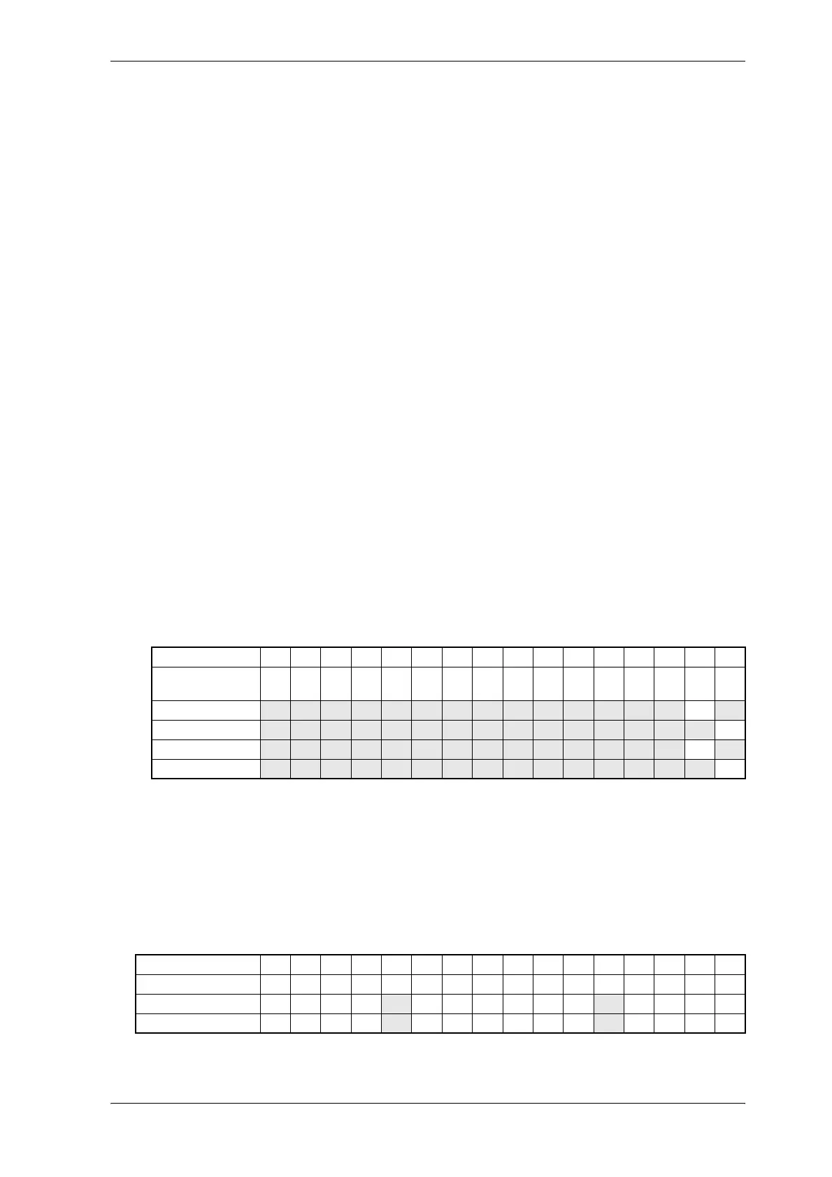
3. The digital input 3 should effect bit no. 4 and 11 of parameter P120.
Set
DI 3 target Pxxx (P378) to 120,
DI 3 bit selection (P379) to 0810,
DI 3 LOW pattern (P380) to 0800,
DI 3 HIGH pattern (P381) to 0010,
Bit no. 15 14 13 12 11 10 9 8 7 6 5 4 3 2 1 0
Example for start
value P013
1 1 1 1 0 0 0 0 1 1 1 1 0 1 0 1
input 1 → HIGH 0 0 0 0 0 0 0 0 0 0 0 0 0 0 0 1
input 2 → HIGH 0 0 0 0 0 0 0 0 0 0 0 0 0 0 1 1
input 1 → LOW 0 0 0 0 0 0 0 0 0 0 0 0 0 0 1 0
input 2 → LOW 0 0 0 0 0 0 0 0 0 0 0 0 0 0 0 0
Bit no. 15 14 13 12 11 10 9 8 7 6 5 4 3 2 1 0
Start value P120 0 0 0 0 0 0 0 0 0 0 0 0 1 1 1 1
input 2 → HIGH 0 0 0 0 0 0 0 0 0 0 0 1 1 1 1 1
input 2 → LOW 0 0 0 0 1 0 0 0 0 0 0 0 1 1 1 1