EasyManua.ls Logo

Baxi DUO-TEC MAX+ - Installing the Flue; Concentric Ducts; Separate Ducts

Baxi DUO-TEC MAX+
Print Icon
To Next Page IconTo Next Page
To Previous Page IconTo Previous Page
Loading...
31
INSTALLER Section (en)
7219623.01 (1-04/15)
10. INSTALLING THE FLUE
              
            
  
ducts using the accessory splitting kit.
WARNINGS
C13, C33

C53
C63 The pressure drop of the ducts must not exceed 100 Pa


C43, C83
For optimal installation, the accessories supplied by the manufacturer should be used.
To optimise operating safety, make sure the ue ducts are rmly xed to the wall with suitable brackets. The brackets must be
positioned over the joints at a distance of approximately 1 metre from one another.
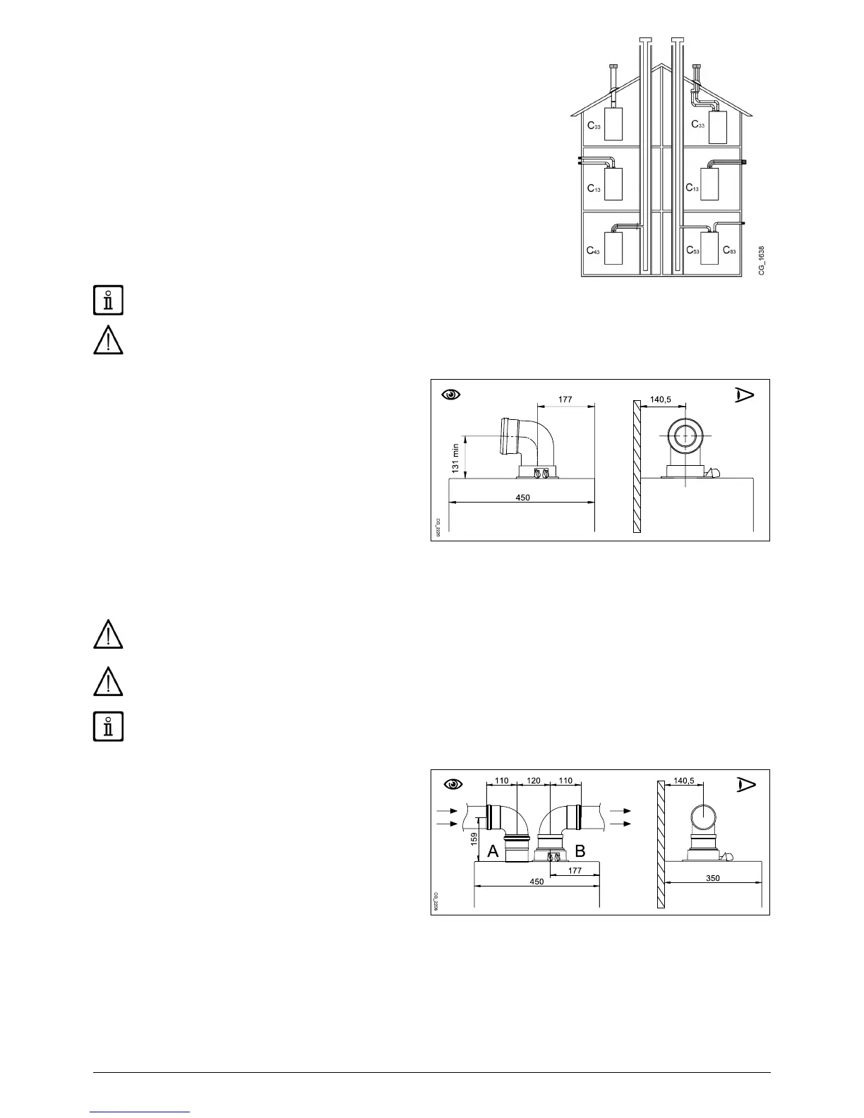
10.1 CONCENTRIC DUCTS






        

        

 A 90° bend reduces the total duct length by 1 metre.
 A 45° bend reduces the total duct length by 0.5 metres.
 The rst 90° bend is not included when calculating the maximum available length.

Before securing the screws, make sure that at least 45 mm of the pipe is inserted into the gasket (see the gures in annex
"SECTION" D at the end of this manual).
Make sure there is a minimum downward slope of 5 cm per metre of duct towards the boiler.
SOME OUTLET DUCT INSTALLATION EXAMPLES AND THEIR RELATIVE MAXIMUM LENGTHS ARE SHOWN IN ANNEX
"SECTION" D AT THE END OF THIS MANUAL.
10.2 SEPARATE DUCTS
This type of installation makes it possible to discharge exhaust
         

         
B) and an air duct adaptor (A). For the

from the cap.
       
outlet ducts, adapting them to various requirements. It can


 A 90° bend reduces the total duct length by 0.5 metres.
 A 45° bend reduces the total duct length by 0.25 metres.
 The rst 90° bend is not included when calculating the maximum available length.

Table of Contents

Related product manuals