33
INSTALLER Section (en)
7219623.01 (1-04/15)
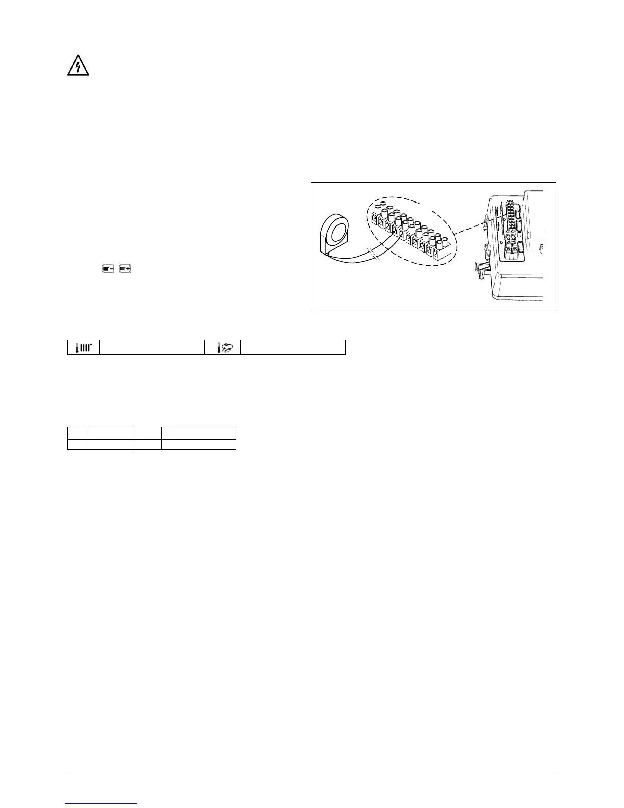
11.1 CONNECTING THE ROOM THERMOSTAT
The connections in terminal block M1 are high voltage (230 V). Before making connections, make sure the appliance is
disconnected from the power supply. Respect polarity L (LIVE) - N (NEUTRAL).
access the terminal block M1
remove the jumper from the ends of contacts 1-2
11.2 ACCESSORIES NOT INCLUDED IN THE SUPPLY
11.2.1 EXTERNAL SENSOR
4-5)
SETTING THE "Kt" CLIMATE CURVE
When the external sensor is connected to the boiler, the
according to the set Kt
pressing
as indicated in the chart in annex SECTION
E for selecting the most appropriate one (00 to 90).
KEY TO CHART - “SECTION” E
Outside temp
11.2.2 CONNECTING TO A ZONE SYSTEM
To use this function, install the programmable relay electronic board supplied as an accessory.
KEY TO ELECTRICAL CONNECTIONS (see diagram in annex "SECTION" G at the end of this manual).
Z Zone (1..n) EV Zone electrovalve
R Relay RT Room thermostat
ambient thermostats can be used to control the other zones.
SYSTEM CONNECTIONS
Connect the zone 1 valve/pump to terminals 1 - 3 of the relay board terminal block inside the boiler control box.
Connect the Ambient Thermostat contact of the other zones to terminals 1-2 of terminal block M1 (CONNECTING THE
AMBIENT THERMOSTAT section).
Check that parameter P04=02. Set parameter P10 (SETTING PARAMETERS section).