7219623.01 (1-04/15) 32
INSTALLER Section (en)
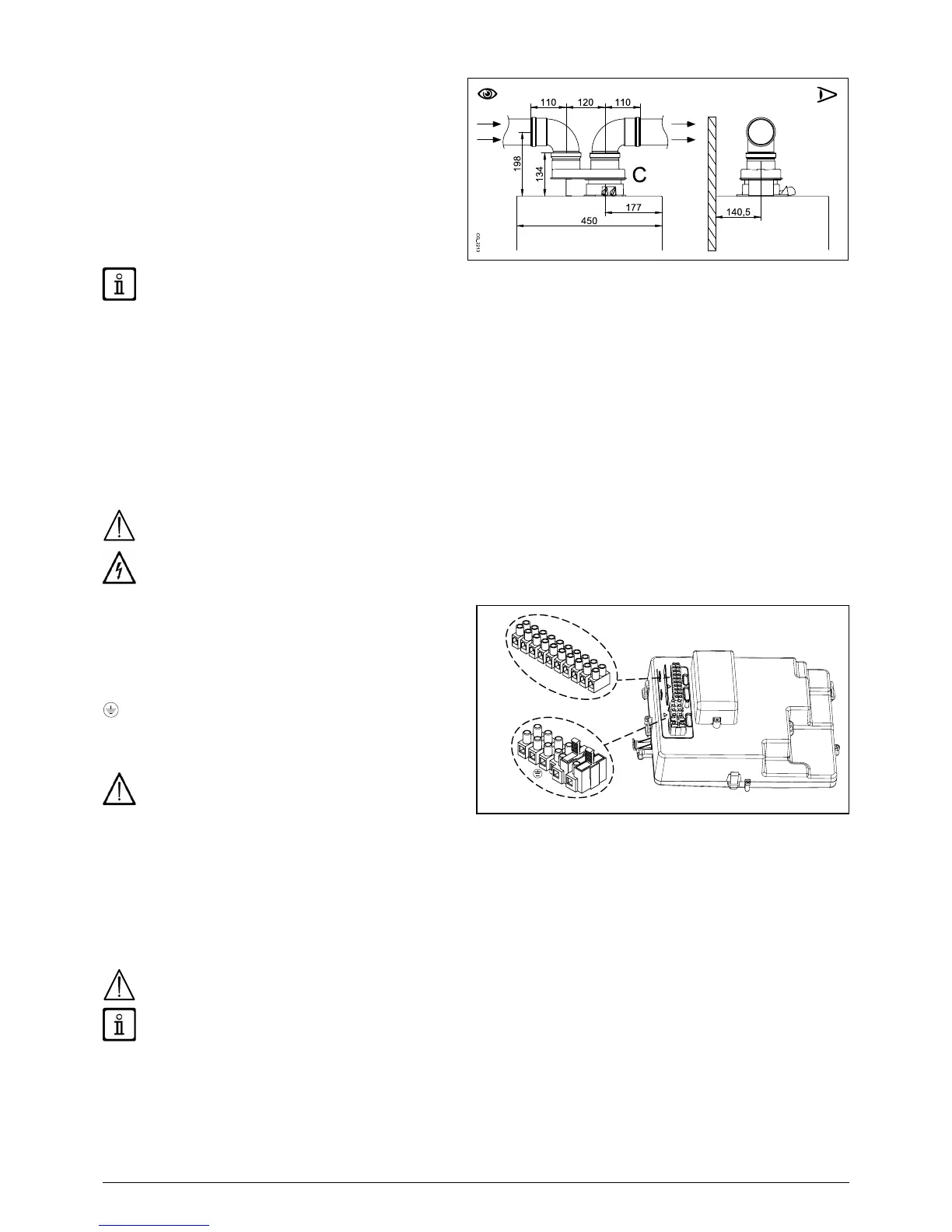
SINGLE SPLITTING KIT (ALTERNATIVE ACCESSORY)
For special installations of the fumes inlet/outlet ducts, the
single splitting kit (C), supplied as an accessory, can be
used. This accessory, in fact, can be used to move the inlet
and outlet in any direction. This type of installation makes
it possible to discharge exhaust fumes both outside the
SOME OUTLET DUCT INSTALLATION EXAMPLES AND THEIR RELATIVE MAXIMUM LENGTHS ARE SHOWN IN ANNEX
"SECTION" D AT THE END OF THIS MANUAL.
11. ELECTRICAL CONNECTIONS
Live-Neutral polarity.
Use a double-pole switch with a contact separation of at least 3 mm.
2
and access terminal blocks M1, M2, M3, used for the electrical connections, after removing the protective cover. The 3.15 A fast-
SEE WIRING DIAGRAM IN ANNEX "SECTION" B AT THE END OF THIS MANUAL
Make sure that the overall rated power input of the accessories connected to the appliance is less than 2A. If it is higher, install
a relay between the accessories and the electronic board.
The connections in terminal blocks M1- M3 are high voltage (230 V). Before making connections, make sure the appliance is
disconnected from the power supply. Respect the input polarity on terminal block M1: L (LINE) - N (NEUTRAL).
TERMINAL BLOCK M1
(L)Live
(N)Neutral (light blue).
Earth
(1) (2)Room Thermostat.
Put back the jumper on terminals 1-2 of boiler terminal
block M1 if the room thermostat is not used or if the
Remote Control, supplied as an accessory, is not
installed.
TERMINAL BLOCK M2
Terminals 1 - 2:
Terminals 4 - 5 (common): external Probe connection (supplied as an accessory)
Terminals 3-6-7-8: not used.
Terminals 9-10: storage boiler sensor connection.
If the appliance is connected to an underoor system, install a limit thermostat to prevent the latter from overheating.
Use the relative cable grommets at the bottom of the boiler to thread the cables through to the terminal blocks.