Fig. 3
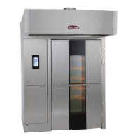
OV500E1 ELECTRIC OVEN
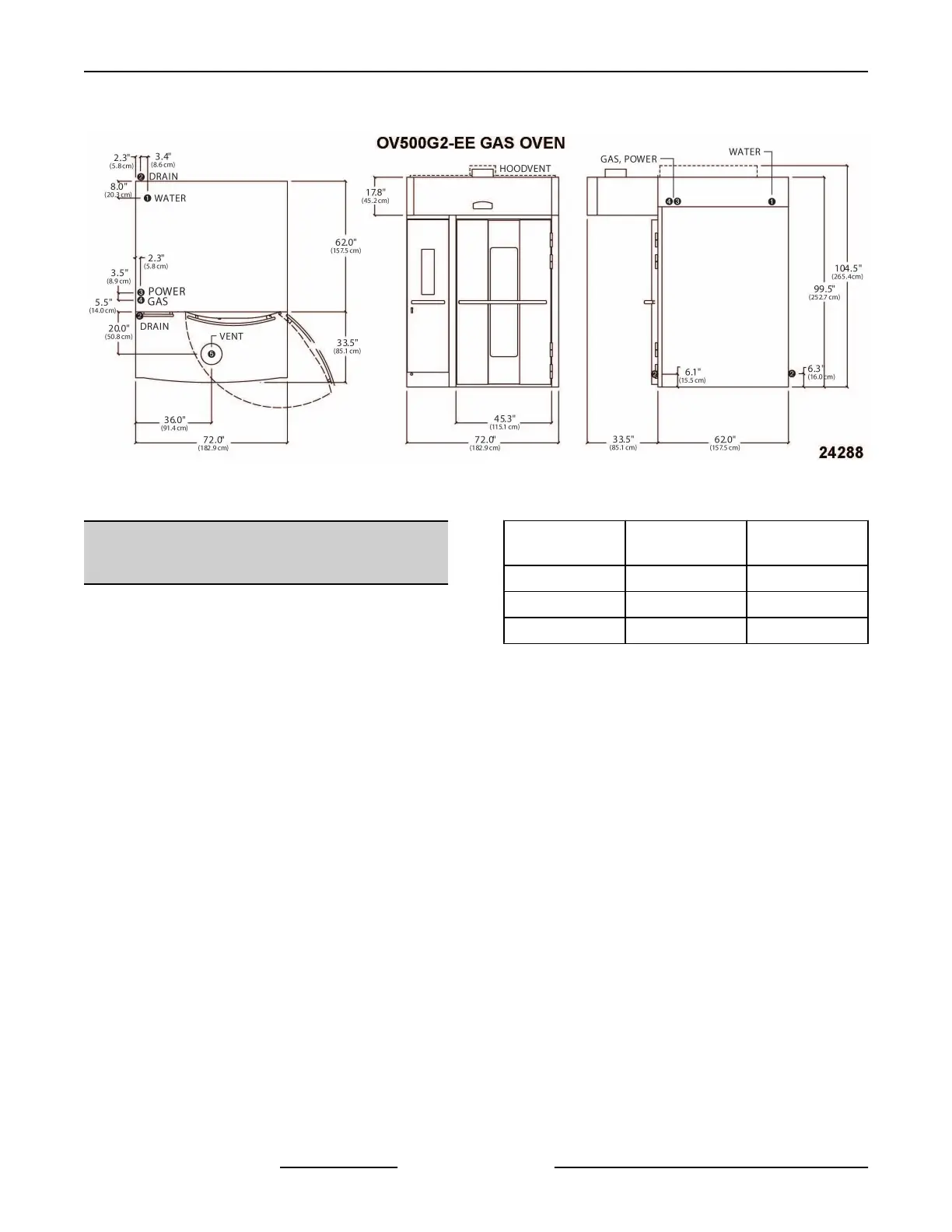
SPECIFICATIONS
1. WATER:
1/2" NPT, 30-75 PSI cold water required,
customer to install in-line filter, shut off valve and
line strainer.
2. DRAIN:
6 1/4" (front) or 7" (rear) connection A.F.F. .
Route to air-gap drain. Do not slope drain
upwards. Plug the drain connection that is not in
use.
Rear Drain: 1/2" NPTF
Front Drain: 1/2" NPTF
3. POWER:
Two supplies required.
120/60/1 20 AMP dedicated circuit required and
one of the following voltage options.
Heating Circuit: KW rating in following chart per
supply voltage.
Blower Motor: 1 1/2 H.P.
Voltage
Full Load
AMPS
Heaters Rating
208/60/3 100 AMPS 34 KW
208 - 240/60/3 76 - 87 AMPS 26 - 34 KW
440 - 480/60/3 40 - 43 AMPS 29 - 34 KW
4. HOOD VENT:
8" DIA connection collar. Customer to supply
duct and ventilator fan per state and local codes.
Oven provided relay with max. 10 amp 1/2 H.P.
@ 120V output for fan operation. If larger, use
oven relay to control additional separately
powered contactor / relay for hood fan. Chamber
vents are factory ducted to this integral hood. 690
CFM required, 0.6" W.C. static pressure drop
through hood. Hood is UL710 Listed when
grease filters are installed. Type B gas vent can
be used except when bake products are grease
laden.
NOTES:
1. A.F.F.: Above finished floor.
2. Customer responsible to finish and install all
utilities to and from oven.
3. All services must comply with all Federal, State
and Local codes.
INSTALLATION INSTRUCTIONS OV500-EE SERIES GAS RACK OVENS AND OV500 SERIES ELECTRIC RACK
OVENS - GENERAL
F45469 Rev. D (1019) Page 12 of 49